Micro-Hydro Power: A Beginners Guide to Design and Installation
By Leif Kindberg, NCAT Energy Specialist
Micro-hydro projects operate efficiently on small streams. Photo: Leif Kindberg, NCAT
Abstract
Farm hydropower projects have existed for many years, from waterwheels used for grinding grain and forging to modern hydroelectric turbines designed to run compressors and motors. Micro-hydro systems — those that produce less than 100 kilowatts of electricity — can offer a sustainable and continuous source of renewable energy on farms. This publication is designed to introduce the reader to all stages of a micro-hydro project — from first considering the idea all the way through to producing power.
Contents
Introduction
Determining the Hydro Potential of Your Site
Environmental Impact
Regulatory Issues
Equipment
Economics
Financial Assistance
Cautions and Suggestions for the Do-It-Yourselfer
Conclusion
Further Resources
References
Appendix: Cost Estimate Worksheet
Introduction
There is a great deal of interest today in using such renewable energy sources as solar power, wind, biomass, and flowing water to produce power to run farm equipment. Many of the technologies for converting these renewable sources into useful power have been with us for centuries and are once again receiving widespread attention. The generation of power from flowing and falling water is no exception. In fact, it is one of the world’s oldest and most common energy technologies. When we think of hydropower, we usually think of big dams and large-scale generation facilities. On a world-wide basis, however, small-scale, environmentally benign mechanical and electrical hydropower systems are very common.
Farms often have easy access to lakes and ponds as well as naturally occurring streams and rivers. When farmers possess the rights to use the water resources that are contained on-farm, they usually face fewer obstacles both in permitting and in the efficient use of farm-scale hydropower. Hydropower can be a continuous source of energy as long as enough water is flowing, and this publication will discuss hydro energy and how to sustainably harvest it. It will not focus on waterwheels, although many of the informational resources that will be discussed are also relevant to developing waterwheel projects.
Electrical power is measured in watts (W), kilowatts (kW), or megawatts (MW), and mechanical power is measured in horsepower (HP). If a turbine generates 150 watts continuously for an hour, it will have generated 150 watt-hours, or 0.15 kilowatt-hours (kWh). Hydropower systems for homes and farms generally have power outputs of less than 100 kilowatts. For convenience in terminology, this scale of hydropower is referred to as micro-hydro.
Micro-hydro systems generally consist of the following components:
- A trash rack, weir, and forebay to prevent debris from entering the pipeline and turbine
- A pipeline (also called a penstock) to pipe water to the turbine
- A powerhouse that contains the turbine and electronics
- A water turbine that converts the kinetic energy of the flowing water into mechanical energy that can be used directly or to drive a generator or other piece of equipment — this is the main component of a micro-hydro system
- A tailrace to release the water back into the source it came from
- Transmission lines to deliver electrical power where it is needed
This publication is intended to include as much information as necessary to get you started in the process and to assist you generally at each step along the way of a micro-hydro project. Actively engaging in the siting and development of your hydropower system is critical, however, because most of this publication serves only to give you guidelines. It is not possible to provide detailed descriptions of every step of the process because micro-hydro development is very site-specific. Each site in each county, state, and region may face a different set of regulations as well as a different ecology, geology, and topography. Also, your personal motivation, economic situation, and farm energy needs are probably very different from the next reader’s.
Determining the Hydro Potential of Your Site
To determine the hydropower potential of the water flowing from your spring or in your stream, you must know both the flow rate of the water and the head. The flow rate is the quantity of water flowing past a point during a given period of time. The flow rates of micro-hydro systems are typically measured in gallons per minute or cubic feet per minute. The head is the vertical drop measured in feet from the headwater (in the case of a dam) or the point where the water enters the pipeline (if no dam exists) to the point where the water leaves the turbine housing. With some turbines, such as those that use a “draft tube,” head extends to the base of the tube.
Flow Measurement
In order to adequately assess the minimum continuous power output to expect from your hydropower system, you will have to determine the minimum quantity of water that will pass through it. For this reason, it is important to know both the minimum flow rate of your stream and what portion of this flow you can use for power generation. It is always important to divert minimum flow for power generation, especially when it will have an impact on fish migration and stream ecology.
If you are already familiar with the stream’s seasonal variations, you can limit flow measurements to the few months surrounding the driest, or lowest, flow. However, if you don’t know approximately when the flow is at its lowest, you will need to make flow measurements at least once a month (twice a month is preferable) throughout the complete year. When determining flow rate, it is best to use either the average flow rate or the lowest flow rate expected during the year. These minimum or average flow rates are especially important when you begin to perform power calculations for your system, which is discussed later in this publication.
| Figure 1. Useful Conversions. |
| Static Head and Pressure 1 foot of head = 0.43 pounds per square inch (psi) of pressure 1 psi = 2.31 feet of head Flow Power *Efficiency not accounted for |
Once your flow data has been compiled, you are in a position to begin some calculations. Was it a dry year or a wet year? To determine this, you will need further information, usually from the U.S. Geological Survey monitoring stations in your area. They will have several years’ precipitation, snowpack, or streamflow data available — if not for your immediate location, then for some nearby major drainage basin. You will have to take a look at this information to see how your measured year fits into the typical patterns for your area. Once you have determined whether your year was dry, typical, or wet, you can make the necessary modifications to your data to determine the minimum expected flow rates for your stream.
If your hydropower system will be producing electricity for a household, you will be most concerned with minimum flows. A good flow sampling through the dry season — assuming you know when the dry season is — will usually be adequate. However, if you are looking at a large project, you might want to estimate more closely the energy demands you expect to place on the system, often called load projections, particularly with respect to what can be done with the energy at the time of year it is available. This will require consideration of the maximum and average streamflows in addition to the minimum. And if your system requires a dam, it is vital to know the maximum streamflow in order to adequately size spillways for bypassing excess water to prevent damage to your installation. The goal is to identify your hydropower system’s “design flow” — the maximum flow for which the system is cost effective and environmentally sustainable to use.
There are several methods for measuring flow. The best method will depend on the type of water resource you plan to measure and the equipment you have available.
For small mountain streams, enclosed drainage pipes, or springs, the bucket method works well. Temporarily dam up the water and divert the entire flow into a container of a known size. Carefully time the number of seconds it takes to fill this container.
For example, if it takes 40 seconds to fill a 55-gallon barrel, the flow rate is 1.375 gallons per second, or 82.5 gallons per minute, or about 11 cubic feet per minute. (See the Useful Conversions table in Figure 1.)
Repeat this process a few times to avoid any errors in measurement and calculation. Then average the rates for a final flow rate.
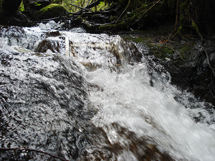
For larger streams from which you expect to use a large quantity of flow, the float method can be used. In order to use this method, you need to know the cross-sectional area of the stream and the stream’s velocity. The cross-sectional area should be determined at some easily measured spot, preferably in the middle of a straight run of the stream. Measure the width of the stream in feet. Also measure the depth of the stream at equal intervals across the width of the stream. (See Figure 2.) Record the depth at each interval and calculate the average depth.
For example (Consider a stream cross-section as shown in Figure 2):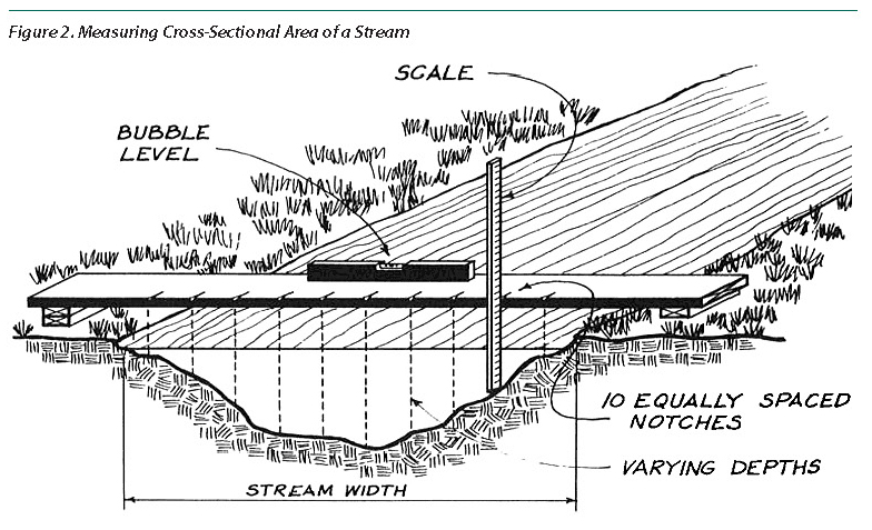
d = depth
d1 = 1.0 feet
d2 = 1.3 feet
d3 = 1.2 feet
d4 = 1.8 feet
d5 = 1.0 feet
d6 = 0.8 feet
d7 = 1.1 feet
d8 = 1.8 feet
d9 = 1.3 feet
d10 = 0.7 feet
Total = 12 feet
Average d = 1.2 feet
Next, multiply the width by the average depth to get the cross-sectional area of the stream in square feet.
For example, in the stream described above, say that the width (w) at the point of making the measurements to determine the average depth (d) was 8 feet. The cross-sectional area (A) can be determined by a simple calculation:
A = w x d
A = 8 feet x 1.2 feet
A = 9.6 square feet
The stream velocity can be determined by choosing a straight stretch of water at least 30 feet long with approximately parallel sides and a bed unobstructed by rocks, branches, or other obstacles. Mark off two points, say 30 feet apart, along the stream. On a windless day, place a float midstream a couple of yards upstream of the first marker. (An orange or a pop bottle partially filled with small stones so that it rides with its neck out of the water work well as a float.) When the float reaches the first marker, begin carefully timing the number of seconds it takes to get to the second marker. To be accurate, repeat this process several times and average the results.
For example, say that the average time for a float to travel between two markers placed 30 feet apart is 15 seconds. Find the velocity of the float:
| 30 feet | ||
|
|
= | 2 feet per second |
| 15 seconds |
The velocity of the float does not, however, represent the velocity of all the water in the stream. Because of friction, the water at the sides and bottom of the stream flows more slowly than the water at the center and near the top of the stream. A correction factor, which is determined by the roughness or smoothness of the streambed, is usually included in an estimate of the average stream velocity. This correction factor can vary from 0.25 for a shallow, rocky creek to 0.75 for a natural stream with a very smooth bed and sides.
For example, take the float velocity computed above to find the stream velocity (V) for a fairly smooth creek with few rocks, boulders, or tree stumps protruding into the streambed:
- V = 2 feet per second x 0.65 = 1.3 feet per second; or V = 78 feet per minute
The flow rate of the stream can now be calculated by multiplying the cross-sectional area of the stream (A) by the stream velocity (V):
- Flow = A x V
- Flow = 9.6 square feet x 78 feet per minute
- Flow = 748.8 cubic feet per minute
Now, depending on what portion of the streamflow you can or want to use (which will be discussed later), you can determine the usable flow. Simply multiply the streamflow rate you have just calculated by the portion of the flow you plan to use.
If you will be using only 25% of the minimum streamflow, and the streamflow you have determined above is 748.8 cubic feet per minute (cfm), finding the usable flow takes another easy calculation:
- Usable flow = 748.8 cfm x 0.25
- Usable flow = 187.2 cfm
You can convert this to gallons per minute (gpm):
- Usable flow = 187.2 cfm x 7.48
- Usable flow = 1,400 gpm
Another method of determining streamflow is called the “weir method.” This method is very accurate and can be used throughout the year to measure the flow rate of any stream. It works particularly well in shallow streams where a float may not float freely.
A weir is usually constructed as a rectangle. To use the weir method in this example, construct a temporary dam across the stream, perpendicular to the flow, with a rectangular notch or spillway that is large enough to take the maximum flow of the stream during the period of measurement. Before constructing the weir, make a rough estimate of the streamflow to size the notch. The notch width (w) should be at least three times its height (h), and the lower edge of the notch should be perfectly level. The lower edge and the vertical sides of the notch should be beveled, with the sharp edge upstream. The whole structure can be built out of timber or plywood, and all the edges and the bottom of the weir should be sealed with clay earth and sandbags to prevent any leaks. Brace and seal the weir very well to ensure that it will not fall or erode around the edges. A typical weir is illustrated in Figure 3.
In order to measure the flow of water over the weir, you have to set up a simple depth gauge. This is done by driving a stake in the streambed at least 5 feet upstream from the weir, until a preset mark in the stake is precisely level with the bottom edge of the weir’s notch. The depth of water on this stake above the preset mark will indicate the flow rate of water over the weir. You will need to refer to a “Weir Table” in order to determine this flow rate. A typical Weir Table for a rectangular notch is provided in Table A. To use the table, determine the depth of water in inches over the preset stake mark. Take this value to the Weir Table and read off the flow rate in cubic feet per minute for each inch of notch width. Multiply this volume flow rate by the width, in inches, of your weir notch. This will give you the streamflow rate in cubic feet per minute.
| Table A. Weir Table. | |||
| Stake depth | cfm/inch of notch width | Stake depth | cfm/inch of notch width |
| 1″ 1.25″ 1.5″ 1.75″ |
0.40 0.55 0.74 0.93 |
13″ 13.25″ 13.5″ 13.75″ |
18.87 19.42 19.97 20.52 |
| 2″ 2.25″ 2.5″ 2.75″ |
1.14 1.36 1.59 1.83 |
14″ 14.25″ 14.5″ 14.75″ |
21.09 21.65 22.22 22.70 |
| 3″ 3.25″ 3.5″ 3.75″ |
2.09 2.36 2.63 2.92 |
15″ 15.25″ 15.5″ 15.75″ |
23.38 23.97 24.56 25.16 |
| 4″ 4.25″ 4.5″ 4.75″ |
3.22 3.52 3.83 4.16 |
16″ 16.25″ 16.5″ 16.75″ |
25.76 26.36 26.97 27.58 |
| 5″ 5.25″ 5.5″ 5.75″ |
4.50 4.84 5.18 5.54 |
17″ 17.25″ 17.5″ 17.75″ |
28.20 28.82 29.45 30.08 |
| 6″ 6.25″ 6.5″ 6.75″ |
5.90 6.28 6.65 7.05 |
18″ 18.25″ 18.5″ 18.75″ |
30.70 31.34 31.98 32.63 |
| 7″ 7.25″ 7.5″ 7.75″ |
7.44 7.84 8.25 8.66 |
19″ 19.25″ 19.5″ 19.75″ |
33.29 33.94 34.60 35.27 |
| 8″ 8.25″ 8.5″ 8.75″ |
9.10 9.52 9.96 10.40 |
20″ 20.25″ 20.5″ 20.75″ |
35.94 36.60 37.28 37.96 |
| 9″ 9.25″ 9.5″ 9.75″ |
10.86 11.31 11.77 12.23 |
21″ 21.25″ 21.5″ 21.75″ |
38.65 26.60 37.28 37.96 |
| 10″ 10.25″ 10.5″ 10.75″ |
12.71 13.19 13.67 14.16 |
22″ 22.25″ 22.5″ 22.75″ |
38.65 39.34 40.04 40.73 |
| 11″ 11.25″ 11.5″ 11.75″ |
14.67 15.18 15.67 16.20 |
23″ 23.25″ 23.5″ 23.75″ |
41.43 42.13 42.84 43.56 |
| 12″ 12.25″ 12.5″ 12.75″ |
16.73 17.26 17.78 18.32 |
24″ 24.25″ 24.5″ 24.75″ 24″ |
44.28 45.00 45.71 46.43 47.18 |
For example, say that on a particular stream you have built a weir with a notch width of 30 inches. The depth of the water on the stake above the preset mark is 6.25 inches. On the Weir Table, read opposite 6.25 inches to the flow rate of 6.28 cubic feet per minute (cfm) per inch of notch width. You can then calculate the flow rate of the entire stream: 6.28 cfm x 30 inches = 188.4 cfm.
When you have the weir in place, you can easily take readings throughout the year. If you are going to use the weir for any extended period of time, it is important to frequently check that the sides and bottom are watertight to prevent water from eroding the soil around it. More information on measuring flow can be found in the ATTRA publication Measuring and Conserving Irrigation Water.
Head Measurement
Just as greater flow provides potentially greater useful power, the greater the vertical distance the water falls, the more potentially useful power there is available in your stream.
“Head” is the vertical distance, generally measured in feet, between your proposed intake location and the proposed power plant. Like flow, head can be measured in several ways, although only a few are accurate enough for designing a hydropower system.
- For high-head systems, topographical maps of your area, which are available from the U.S. Geological Survey, may give some indication of the vertical distance between your intake and tailrace of the hydro turbine. However, topographical maps are not always accurate and should only be used for preliminary estimates of head, not for power calculations or sizing turbines.
- Altimeters and GPS units with an altimeter function can provide estimates of the elevation difference between the intake and tailrace locations, but they should not be used for the final measurement. It is common for inexpensive barometric altimeters to be in error by 150 feet or more when calibrated (New, 2004).
- A graduated pressure gauge can be fitted on the end of a hose. One end of the hose should be positioned at the intake location, and the other end should steadily decline to the turbine location. Fill the hose with water and read the gauge. (Be sure to purge any air in the hose by running water through it for a few minutes before attaching the gauge.) Convert the pressure reading into a measurement of head by multiplying the pressure in pounds per square inch (psi) by 2.31. For example, a reading of 50 psi would be calculated 50 x 2.31 = 115.5 feet of head.
- Using a surveyor’s transit can be a very accurate method of measuring head and is ideal for sites with less than 50 feet of head. It is easiest to have an assistant to help measure head when using a transit.
- Head can be measured fairly accurately with a laser level, sight level (peashooter), or a carpenter’s level with some sort of stand to raise it a few feet off the ground. To use a carpenter’s level, you will also need a tape measure and pencil and paper. An assistant may make the job easier.
a. Set up your level, making sure that it is horizontal (level) and that its upper edge is at the same elevation as the proposed intake location — or at a known vertical distance above the location.
b. Sight along the upper edge of the level to a spot on an object farther down the hill (e.g., a measuring rod, tree, rock, or building) that can be reached for measuring.
c. Note this precise spot on the object and mark it (Point A in Figure 4 below).
d. Move your level and your stand down the hill and set them up again, with the upper edge of the level at some Point B below Point A, as shown in Figure 4. Mark this point B and measure and record the vertical distance A to B. Now sight along the upper edge of the level again to another point A that is farther down the hill to get your next point.
e. Repeat this procedure, identifying and measuring points until you reach the proposed location of the hydro turbine.
f. If more than one setup was required, add all the vertical distances between the paired A and B points. If your first setup was above the water surface near the intake location, subtract the vertical distance between the water surface and the upper edge of the level from the sum of the vertical distance. You now know the total head of your proposed site.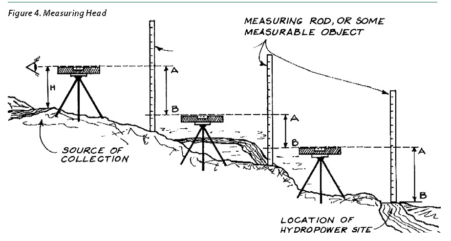
When using this method to calculate head, there are a few things to remember:
You do not need to be concerned with horizontal distances for head determination.
Every time you reset the level, its upper edge should be at precisely the same level as Point B (sight back to check this).
The line of travel can meander along the most suitable path to run the penstock.
Once you have the total, or gross, head, there are various losses in the penstock to consider before you can make any theoretical power calculations. The net head is required for these calculations: net head = gross head – losses in the penstock.
Losses occur for several reasons. There are friction losses whenever water flows through a pipe or makes a quick turn. These friction losses become greater with increased flow rates, and they also depend on the size of the pipe being used — the smaller the pipe’s diameter, the greater the friction. Elbows and bends in the pipe also will increase friction losses. Typical pipe losses for polyvinyl chloride (PVC) pipe are indicated in Figure 5, and pipe-friction calculators are available online.
| Figure 5. Head Loss Chart | ||||||||||||||
| Design Flow | ||||||||||||||
| GPM | 25 | 50 | 100 | 150 | 200 | 300 | 400 | 500 | 600 | 700 | 800 | 900 | 1000 | 1200 |
| CFS | .05 | .1 | .2 | .33 | .45 | .66 | .89 | 1.1 | 1.3 | 1.5 | 1.78 | 2.0 | 2.23 | 2.67 |
| PVC Pipe Size and Head Loss Per 100 Feet | ||||||||||||||
| 2″ | 1.28 | 4.65 | 16.8 | 35.7 | 60.6 | 99.2 | ||||||||
| 3″ | .18 | .65 | 2.33 | 4.93 | 8.36 | 17.9 | 30.6 | 46.1 | 64.4 | |||||
| 4″ | .04 | .16 | .57 | 1.23 | 2.02 | 4.37 | 7.52 | 11.3 | 15.8 | 21.1 | 26.8 | 33.4 | ||
| 6″ | .02 | .08 | .17 | .29 | .62 | 1.03 | 1.36 | 2.2 | 2.92 | 3.74 | 4.75 | 5.66 | 8.04 | |
| 8″ | .04 | .07 | .15 | .25 | .39 | .5 | .72 | .89 | 1.16 | 1.4 | 1.96 | |||
Any reputable pipe manufacturer or supplier will be able to provide you with the pipe options and friction-loss information for your particular flow conditions. Subtract the pipe losses from your gross head to get net head. Other losses that might occur in your hydro system depend on the number of pipe turns it contains as well as the valves, reducers, and type of turbine that you will be using.
Power Calculation
Once you have determined the usable-flow rate and the net head for your particular site, you are in a position to calculate a rough estimate of the amount of power you can expect from the site. You will first have to calculate the theoretically available power, which is a measurement that assumes that 100% of the power available to the turbine can be converted to a useful form.
There are multiple calculations that can be used to project theoretical power. The theoretical power available (Pth) is given by the following equation (where 62.4 = density of water, in pounds per cubic foot; Q = usable flow, in cubic feet per minute; and h = net head, in feet):
Pth = 62.4 Q x h
This gives Pth in foot-pounds per minute.
To convert to horsepower, the equation becomes:
| 62.4 Q x h | ||
| Pth | = |
|
| 33,000 | ||
| Q x h | ||
| Pth | = |
|
| 529 | ||
To convert to kilowatts, the same equation becomes:
| 62.4 Q x h | |||
| Pth | = |
|
x 0.746 |
| 33,000 | |||
| Q x h | |||
| Pth | = |
|
|
| 709 | |||
For example, using a flow rate (Q) of 5 cubic feet per minute and a net head (h) of 100 feet, here is the calculation to determine the theoretical power in kilowatts:
| Q x h | ||
| Pth | = |
|
| 709 | ||
| 5 x 100 | ||
| Pth | = |
|
| 709 | ||
-
- Pth = approximately 0.7 kilowatts
-
- or Pth = 700 watts
The calculation of the theoretical power available represents more power than you will get out of your equipment because some energy is always lost when it is converted from one form to another. All of the machinery and other equipment that you use to convert the power available in the flowing water (kinetic energy) to mechanical-shaft or electrical power is less than 100% efficient.
Losses occur if your system must transfer power from the turbine to the generator, alternator, or some mechanical system. Belt drives can be estimated to have an efficiency of between 95% and 97% for each belt (direct-drives are a better option); gear boxes have 95% or higher efficiency; and alternators and generators are about 80% efficient. Equipment and turbine manufacturers should be able to provide at least an estimate of efficiencies for their products.
Typical overall efficiencies for electrical generation systems can vary from 50% to 70%, with higher overall efficiencies of 70% to 85% occurring in high-head, high-speed impulse systems.
For example, using our previous figures, the theoretical power available (Pth) was 700 watts. If an impulse turbine with efficiency of 80% is used with a single belt drive to an 80% efficient alternator, then it is reasonable to expect that the useful power (P) is:
- P = 700 watts × 0.8 (turbine) × 0.95 (belt drive) × 0.8 (alternator)
- P = 426 watts
For preliminary power calculations, you need to focus only on the previously mentioned efficiency losses. Before moving on to site development, however, you will want to include all efficiency losses, which include pipeline-friction losses (if not already included), power-line losses, battery-charge losses, and losses related to inverter efficiency. After including all efficiency losses, you now have what is commonly called the “water-to-wire” efficiency factor.
In summary, here are the steps to follow to determine the hydropower potential of your site:
-
- Measure the water-flow rate, preferably using one of the following:
- Timed container-filling method
- Float method
- Weir method
- Determine the usable flow — that portion of the streamflow you can use.
- Measure the total, or gross, head, preferably using one of the following:
- Surveyor’s equipment
- Carpenter’s level and stand method
- Determine the net head by subtracting friction and other head losses from the gross head.
- Measure the water-flow rate, preferably using one of the following:
-
- Calculate the theoretical power (Pth) available using either of the following equations (where Q = usable flow rate, in cubic feet per minute; and h = net head, in feet):
Q x h Pth =
to find horsepower 529 Q x h Pth =
to find kilowatts 709
- Calculate the theoretical power (Pth) available using either of the following equations (where Q = usable flow rate, in cubic feet per minute; and h = net head, in feet):
-
- Calculate the useful power available by multiplying Pth by the efficiency of each piece of equipment linked into the system.
If you have come this far on your own — having calculated the head, flow, and potential power output — and think you are on your way to selecting and installing equipment, it is worthwhile to pause for a moment to consider other issues that can arise as you develop your hydro site. Initiate a conversation with the power company, regulatory agencies, and other local, state, and federal entities that may be involved in your project.
| Figure 6. Typical Power Output (In Watts) with Various Head and Flow Rates. | ||||||||
| Flow Rate | ||||||||
| Head | (cfm) | 10 | 15 | 20 | 25 | 30 | 35 | 40 |
| (ft) | (gpm) | 75 | 112 | 150 | 187 | 224 | 262 | 299 |
| 7 | 49 | 74 | 99 | 123 | 148 | 173 | 197 | |
| 13 | 92 | 138 | 183 | 229 | 275 | 321 | 367 | |
| 26 | 183 | 275 | 367 | 458 | 550 | 642 | 733 | |
| 33 | 233 | 349 | 465 | 582 | 698 | 815 | 931 | |
| 49 | 346 | 518 | 691 | 864 | 1,037 | 1,209 | 1,382 | |
| 66 | 465 | 698 | 931 | 1,164 | 1,396 | 1,629 | 1,862 | |
| 98 | 691 | 1,037 | 1,382 | 1,728 | 2,073 | 2,419 | 2,764 | |
| 131 | 924 | 1,386 | 1,848 | 2,310 | 2,772 | 3,233 | 3,695 | |
| 197 | 1,389 | 2,084 | 2,779 | 3,473 | 4,168 | 4,862 | 5,557 | |
| 262 | 1,848 | 2,772 | 3,695 | 4,619 | 5,543 | 6,467 | 7,391 | |
| 295 | 2,496 | 3,121 | 4,161 | 5,201 | 6,241 | 7,281 | 8,322 | |
| Includes a “water-to-wire” efficiency factor of 50% | ||||||||
Environmental Impact
The environmental impact of micro-hydro systems is usually small but by no means absent altogether. When water is diverted or dammed, or when structures installed in the stream channel interfere with the natural flow of the water, there is an environmental impact. However, compared to large hydropower dams, micro-hydro systems have a smaller footprint and generally lower environmental impacts. Even so, there are several local, state, and federal agencies that may want environmental impacts to be assessed for a micro-hydro project.
There are a number of environmental considerations for micro-hydro systems. Among them are the following:
- Water-quality issues such as turbidity and sediment from the system’s construction and operation
- Diversion of streamflow creating lower flow conditions in the main stream channel
- Wildlife and migratory-fish impacts
- Historical significance and aesthetics
- Changes in and impacts on stream ecology (e.g., algal communities, changes in food chains, stranding of benthic invertebrates living on the bottom and banks of the stream, and loss of aquatic habitat)
- Changes in nutrient transport and cycling
- Changes in water temperature due to lower flow
- Changes in dissolved-oxygen levels
Micro-hydro systems that are nonconsumptive and “run of river” — meaning that the natural water flow and elevation drop is used to generate power and the water is directed back into the stream — generally have a small environmental impact. This is an important point to remember and communicate when local regulators ask about environmental impacts. However, diverting water out of the steam, even temporarily, affects the stream’s ecosystem. For example, diverting too much of the water for even a short distance can prevent the natural migration of aquatic organisms and raise the water temperature enough to kill aquatic life. These effects can be compounded if other ecosystem changes also occur, such as the removal of streamside brush or timber that was providing stream shading and other ecological benefits. Not only will the immediate stream ecology be affected, but the downstream ecology is likely to change as well. This, of course, depends on your particular case — are you using a run-of-the-river system or stored pondage? Maybe your system is on a high-head stream and will have limited or no impact on fish or other aquatic organisms. Always carefully plan your system to prevent salamanders, snakes, crawdads, and other aquatic creatures from entering the pipeline and turbine or being otherwise harmed.
The in-stream flow requirement is an important consideration for micro-hydro sites. This is the amount of water needed in the stream to sustain its resource values at acceptable levels. These values include the support of fish and wildlife populations, recreation, hydropower generation, navigation, and ecosystem maintenance—including freshwater flowing to estuaries, riparian vegetation, and floodplain wetlands (McKinney et al., 1983).
Intakes should be carefully located to take on characteristics of the natural stream flow. Photo: Leif Kindberg, NCAT
Projects should be designed to divert the minimum amount of water required. In many areas, streamflow fluctuates with drier and wetter periods of the season. Many sites will not always have a sufficient streamflow to both provide water to the turbine and maintain a low environmental impact. Therefore, the volume of water diverted to the turbine must be managed. In many areas of the U.S., including the Ozark Mountains and Appalachian Mountains, this may require that diversions and penstocks be shut off during dry periods of the year. Of course, this would affect your hydropower system’s “design flow.”
There are simple design considerations that can help mitigate a hydropower system’s environmental impacts. For example, an intake placed in the water channel should be located where it takes on characteristics of its environment.
To learn more about how your project will affect the environment, visit the biology department at your local university or talk to an aquatic biologist at your local fish-and-game department office. By doing such research in advance, you will be prepared to answer questions as you prepare to permit the project.
The relatively small environmental impact of a well-designed micro-hydro system means it can be a sustainable solution to energy needs. However, if your project is near public areas or a neighbor’s property, what it looks like can significantly affect the public’s opinion of that impact. In fact, thoughtfully integrating micro-hydro equipment into the natural landscape may help reduce its environmental impact. Remember, micro-hydro projects that produce renewable power and avoid visually disturbing the natural environment with the intake, pipe, cables, and other equipment demonstrate how to produce energy in a more sustainable manner.
Hydro Power for Gravity Flow Irrigation Systems
Roger and Shelley Barton own and operate Barton Farm in Ferron, Utah. The Bartons farm 120 acres of alfalfa and mixed grasses used for horse hay. They irrigate with a center-pivot irrigation system. Diesel fuel is a large expense in operating a center pivot. The Bartons needed to reduce fuel costs and still follow their irrigation schedule. By using a Cornell hydro turbine to produce mechanical power, the Bartons eliminated their irrigation fuel costs while also reducing the environmental impact of burning fossil fuel.
The combination of a hydraulic center pivot and a hydro turbine is generally a good match when available pressure exceeds the requirements of the irrigation system by 40 pounds per square inch or more. The Bartons receive irrigation water by gravity feed from a reservoir several miles away, which provided 80 pounds per square inch of operating pressure at the pivot point, 37 pounds per square inch more than required to operate 1,220 feet of pivot and the end gun. The T-L hydraulic pivot installed at the Bartons’ farm requires 15 horsepower to operate correctly.
System Specifications:
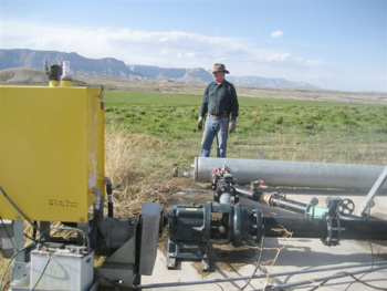
Roger Barton has eliminated all irrigation fuel costs by integrating a hydro turbine into his existing center pivot. Photo: Courtesy of Roger Barton
Hydro resource: Gravity flow from reservoir
Total pressure: 80 pounds per square inch
Additional pressure: 37 pounds per square inch
Head: 162 feet
Flow: 888 gallons per minute
Irrigation system: T-L hydrostatic center pivot
Hydro turbine: Cornell Turbine (5TR5-F16)
Runner type: Francis
Pipe: 10-inch steel with compression fittings
Total system cost: $17,000 (before cost share)
Incentives: $4,000
Cost savings estimate: $4,000 annually
Simple payback estimate: 4 years
Regulatory Issues
A key part of any micro-hydro project is obtaining the necessary permits from local, state, and federal agencies. Although the permitting process may appear burdensome, it is intended to protect the water resource and its users, including the fish, plants, and animal communities that also use the water. It is best to identify all the necessary permits and approvals to develop a hydro resource very early on in the process. Doing so will help you avoid wasting time in planning your micro-hydro project.
In general, the following issues will need to be addressed in order to develop a hydro resource legally:
- Water rights
- Dam safety compliance (if applicable)
- State and federal environmental considerations and compliance
- Historical and archeological considerations
- State land-use permits
- Local construction permits
The first step is to determine the ownership of water rights for the resource being considered. Law pertaining to water rights varies greatly across the country, and a close examination of regulations in your area is important. Talk with any other micro-hydro project owners in your area to learn what they have done. Generally, you should not assume that because you own the land, you also own the water that runs across it. In many states, it is possible to buy land without water rights or to buy water rights without owning the land along with them. A property owner downstream may own the first right to use water upstream from that property, or the water may be owned by several downstream users, with each allowed to take some percentage of the flow. In many states, the fact that your hydro system will only use, not consume, water will not be enough to avoid needing a permit; you must have the legal right to use the water and obtain a permit to use it in many areas. The water rights for particular sites may go back a great many years, and researching old records may be necessary to determine the true holder of those water rights.
Much of the state law regulating water usage was written relative to its irrigation and domestic consumption, and thus is not directly applicable to hydropower systems that are non-consumptive. This may require new legal decisions in some cases and could mean some hesitancy on the part of regulatory-agency personnel. Do not be discouraged, and do not give up if the first response to your inquiry is “no.”
A second step is to secure a water-use permit, which, in some cases, may be required from both state and federal agencies. In some states, having the legal right to the water is all that is required. In other cases, an additional permit is required referring to a specific intended use. Here again, most water-use laws are oriented toward agricultural uses, and questions may arise relative to their interpretation in the context of a micro-hydro project. Often, the actual installation work must begin within some time period or the permit will expire and must be applied for again.
A federal use permit is generally required when the resource or its development involves federal land, be it under the control of Forest Service, Bureau of Land Management, or any other agency. An important point to remember is that your use is beneficial and non-consumptive — 100% of the water is returned to the stream. This is different from agricultural or industrial uses, which may be beneficial but are also consumptive. Be certain to mention that your intended use is beneficial and non-consumptive; it should help in the permit process.
The Federal Energy Regulatory Commission (FERC) is the agency that issues exemptions and licenses for non-federal hydropower projects. FERC also provides guidance concerning state and federal agencies you will need to contact regarding many of the environmental and historical issues related to a hydropower project. Because most hydropower projects have tended to be very large, with significant regulatory issues involved, the FERC licensing process has historically been a lengthy effort. Because of growing interest in small and micro-hydro projects, FERC provides permitting guidance online through the Small/Low-Impact Hydropower Program to help small hydropower projects move quickly through the licensing process. (See the Further Resources section in this publication.) FERC has the authority to issue exemptions for projects under 5 megawatts (all micro-hydro projects fall under this threshold) and when projects use existing conduits (such as an irrigation canal) being used for purposes other than hydropower. Applying for an exemption is free but requires patience. The average wait from submitting an application to receiving an exemption is six to 12 months.
There are several project-design considerations that can help you move through the FERC permit or exemption process quickly:
- Locate the project at an existing dam or conduit
- Develop a project that produces less than 5 megawatts
- Design the project to create little change to water-flow characteristics
- Avoid areas with endangered species or fish-passage issues
- Document the rights needed for project construction and operation
- Provide existing information on environmental resources in the project area
- Address any issues that have been identified
- Identify the key federal and state agencies, tribes, citizen groups, and other stakeholders likely to have an interest in your project
- Meet with the stakeholders as soon as possible in the planning process
- Provide stakeholders with sufficient information to describe your project
- Complete a detailed application that addresses all pertinent issues
Small- and low-impact projects may have a simpler permitting process than larger projects, but that does not mean they are exempt from the jurisdiction of such federal and state agencies as the Corps of Engineers, fish-and-wildlife agencies, and other agencies that establish building codes. Many small hydropower projects have been developed without going through the official permitting process required by FERC and other agencies. There are risks associated with doing so, however, including the possibility of an order to stop operating the system you have just paid to install. It is recommended that developers of small hydropower projects determine whether they are subject to FERC and other local, state, and federal regulations before developing a hydropower site.
Permitting may be the most cumbersome and time-consuming process of your small hydro project. The process may go more smoothly if you review the FERC Small/Low-Impact Hydropower Projects website, communicate regularly with relevant agencies, and take the time to provide a comprehensive application package.
Equipment
Turbines
A water turbine is basically a device that converts the energy in moving water into rotating mechanical energy. This energy, available in a rotating shaft, may be used directly to operate such mechanical equipment as a grain grinder, saw, or other shop equipment, or it may be hooked up to a generator to produce electricity. Although this section will deal primarily with the generation of electricity, a discussion of and references to mechanical applications also are included.
| Figure 9. Typical Efficiency of Turbines. | ||
| Turbine | Head | Efficiency |
| Impulse Turbines | ||
| Pelton | High (>98 ft.), Medium (32-98 ft.) | 80-90% |
| Turgo | High (>98 ft.), Medium (32-98 ft.) | 80-95% |
| Cross-flow | Medium (32-98 ft.), Low (<32 ft.) | 65-85% |
| Reaction Turbines | ||
| Francis | Medium (32-98 ft.) | 80-90% |
| Pump-as-turbine | Medium (32-98 ft.) | 60-90% |
| Propeller | Low (<32 ft.) | 80-90% |
| Kaplan | Low (<32 ft.) | 80-90% |
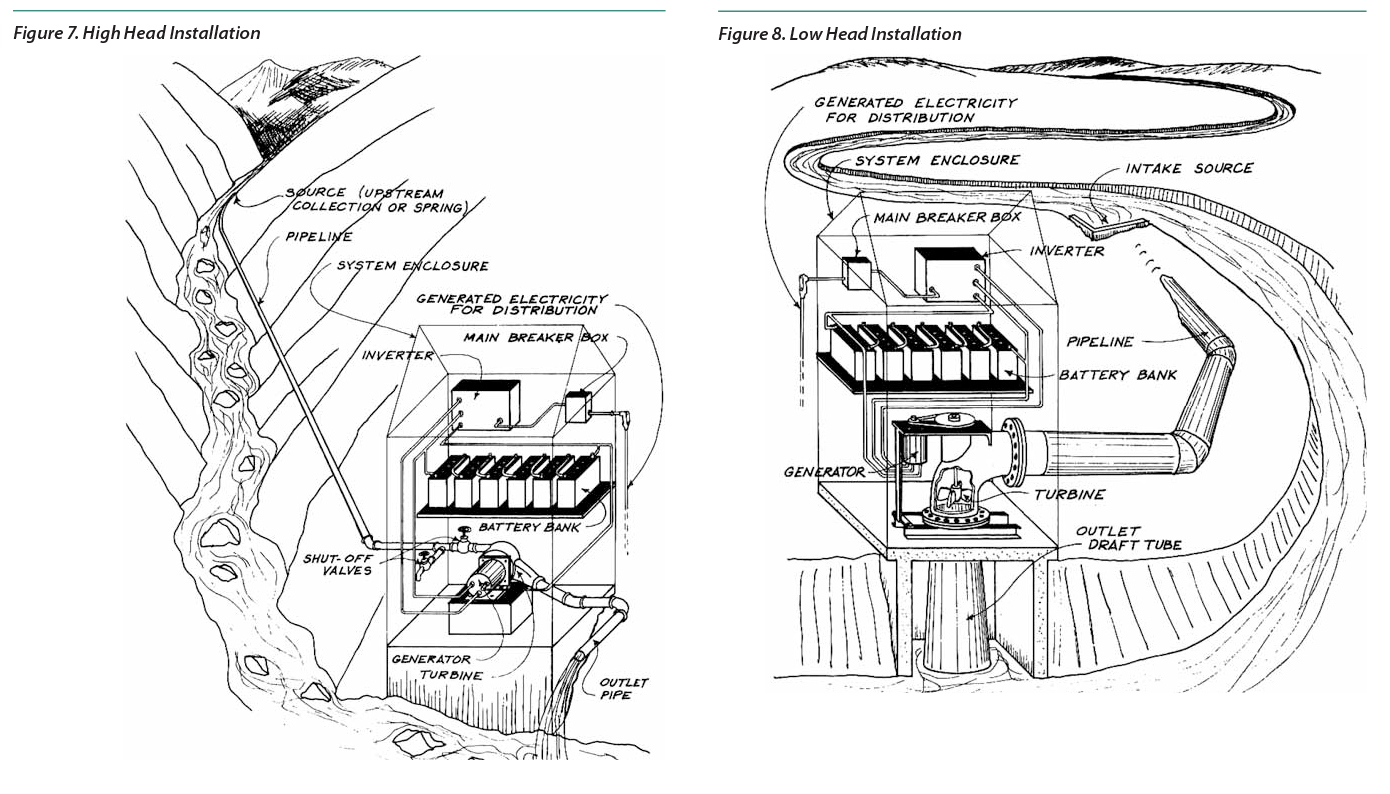
The energy potential that is available at a hydropower site is the result of the combination of the “head” and “flow” that is present. It is possible to produce power with many combinations of head and flow. Sites with 60 feet or more of head are considered “high head.” It is also generally assumed that a head of about 3 feet or 1 meter is the absolute minimum needed to develop hydropower, but a head of less than 10 feet is probably uneconomical to develop in most situations. Although high-head, high-flow sites are generally the most economical to develop, sites with a combination of high head and low flow or vice versa are more common and also can be economically developed, depending on your energy needs.
Hydro turbines are generally very efficient in converting the energy available in the water resource into mechanical or electrical energy. In fact, turbine efficiencies of 70% to 85% are not uncommon. Turbines are usually designed for a specific application and output. Therefore, you will generally gain nothing by installing a unit that is larger than your water resource is capable of using. It is important to have a good understanding of your energy requirements and the characteristics of your water resource before selecting a turbine.
Impulse Turbines
Impulse turbines generally use the velocity of the water to move the runner (or wheel) rather than using pressure, as is in the case with reaction and propeller designs. Consequently, there is no suction on the down side of the turbine, and the water simply falls out of the bottom of the turbine housing after hitting the runner. Impulse units are generally the simplest of all common turbine designs and are widely used in micro-hydro applications. There are three common impulse runners: the crossflow turbine, the Pelton wheel, and the Turgo wheel.
The Crossflow Turbine
A crossflow turbine is drum-shaped, with the blades fixed radially along the outer edge. The turbine is open in the center, resembling a “squirrel cage” blower. From the perspective of looking at the turbine at its end — as though it were a clock face — the water enters at 9 o’clock, crosses the center and exits at 4 o’clock: thus the name crossflow. Because of its design, the crossflow is considered to be largely self-cleaning and is well suited for low-head applications. Because the runner and housing fit fairly closely, a draft tube is used on the down side of the turbine, allowing some flexibility in installation relative to turbine placement and tail-water level.
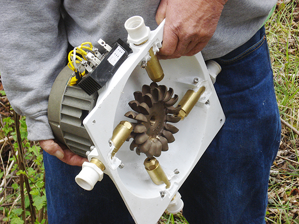
A custom built four-nozzle hydro turbine with a bronze Pelton wheel and a brushless permanent magnet alternator. Photo: Leif Kindberg, NCAT
The Pelton Wheel
In general terms, a Pelton wheel is a disc with paddles or cups attached to the outside edges. The water passes through one or more nozzles and strikes the cups one at a time, causing the wheel to spin. The shape and the smoothness of the cups are important. The cups are shaped so that the water stream is split in half and begins to reverse direction. The wheel speed is regulated to harvest the maximum energy in the water jet before the water drops straight down into the tailrace. Because the power developed by the Pelton wheel is largely dependent on the velocity of the water, it is well suited for high-head, lowflow installations. Operating efficiencies in the 80% range are common, and micro-hydro turbines using the Pelton wheel are available from several companies in North America.
The Turgo Wheel
The Turgo wheel is a variation of the Pelton wheel. The Turgo runner is a cast wheel whose shape generally resembles a fan blade that is closed on the outer edge. The water jet is applied to one side, goes across the blades, and exits on the other side. The advantage of this design is that power equivalent to the Pelton can be produced with a smaller wheel at higher speed. As with the Pelton, it is possible to use more than one water jet on a single wheel in situations where relatively lower head and higher flow are present. Also like the Pelton, the wheel itself can be used with different nozzle sizes to match the equipment to site conditions.
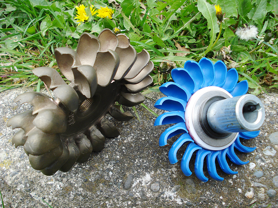
At left is a 4-inch pitch diameter Pelton wheel, and at right is a 3.24-inch pitch diameter Turgo wheel. Such wheel designs are common in micro-hydro systems. Photo: Leif Kindberg, NCAT
Reaction Turbines in General
Reaction turbines work on a different principle than impulse designs. Reaction turbines use pressure rather than velocity. They function more like a centrifugal water pump running in reverse, which will be discussed below. The runner is placed directly in the water stream, and power is developed by water flowing over the blades rather than striking each individually. Reaction turbines tend to be very efficient at sites specifically designed for them, and their efficiency falls sharply with any variation. The Kaplan design, as we will see, is intended to address that problem. Reaction units are often used in very large installations such as hydropower dams as well as high-flow, low-head micro-hydro systems.
The Francis Turbine
Francis turbines are typically installed in very large hydropower developments. The water is introduced just above the runner and all around it and then falls through, causing the runner to spin. Francis units are designed very specifically for their intended installation and use a complicated valve system, so they are not generally used in micro-hydro applications.
Propeller Turbines
The propeller turbine resembles a boat propeller, usually running in a tube, and operates on a similar principle. As with
the Francis, the water contacts all of the blades constantly, and it is thus imperative that the propeller receive a high and continuous flow. Without uniform and sufficient flow, the pressure on the propeller blades will be inadequate to produce useful power. The Kaplan propeller turbine has adjustable blades on the propeller to allow for variations in flow rates. Depending on site conditions, the unit can be installed in any position from horizontal to vertical.
Pump-as-Turbine (PAT)
Centrifugal pumps can be operated like a hydro turbine by running them in reverse. Pumps are often combined with a motor via a direct drive and used as a generator set. A “pump-as-turbine,” or PAT, is an inexpensive alternative for small hydropower systems. It is estimated that the cost of a PAT is 50% or less than that of a comparable turbine (Natural Resources Canada, 2004).
Centrifugal pumps are readily available, usually inexpensive, and manufactured in a variety of sizes that can accommodate many heads and flows. However, they are usually limited to a narrower flow range in comparison to a typical hydro turbine. At some sites, two or more PATs are installed, and the flow is switched from one turbine to the other during seasonal variations. However, the cost associated with installing two PATs may outweigh the benefit of using just one conventional hydro turbine that can be adjusted to seasonal variations in site conditions.
A PAT usually includes an integrated induction (asynchronous) motor. The induction motor is used with a PAT as the generator, while a synchronous generator is more often used in battery-based installations with a conventional hydro turbine. Induction motors are commonly available, less expensive than a comparable synchronous generator, and very durable. To be used in a PAT system, their winding connections will usually need to be modified and they will usually need additional capacitors. More information on PATs can be found in the Further Resources section at the end of this publication.
Sizing the System
It is important to examine your power needs and the characteristics of those needs early in your project, while keeping in mind that saving energy is almost always cheaper than constructing a larger system. There are two separate but related questions to ask yourself: What is my total consumption? And what is my peak consumption?
The total consumption is the number of kilowatt hours used in a given period of time. If you are presently getting your power from the local utility, you need only check a number of past bills to get this information. Keep in mind that most household consumption varies by the month and season, with unusual changes in weather, or with a change in the number of household members. For example, taking consumption figures for the months of June, July, and August may not reflect true annual averages. It is important to obtain a good estimate of your average energy needs and also to consider any energy efficiency or conservation measures that can be used to reduce your power requirements.
The peak consumption can be considered to be the maximum amount of power required at any one time. This means that if several electrical items are operating at once and others simultaneously start up, the resulting power consumption will be the peak. In micro-hydro systems, the peak will be more likely to cause you problems than will the total consumption. Situations with a high peak load relative to the average load will be less efficient and more costly than situations in which consumption is more uniform. Seasonal farm loads such as irrigation pumping, grain grinding, and refrigeration will need to be calculated for individual situations. When analyzing your situation, consider whether there are operating practices that can be adjusted to reduce peak power needs rather than constructing a system that can cover a high peak-consumption pattern.
One way to size hydroelectric systems is simply to design them to meet all your power needs and divert any excess power into uses such as baseboard heaters, lights, or hot water. Hydropower is a very inexpensive energy resource if you take a long-term view of the costs. Another option is to size the system to meet the average power consumption and use battery storage to meet peak power consumption. For sites with small output potential, the system may require the use of batteries in order to meet peak consumption. On the other hand, if you have access to the utility grid, it will be possible to purchase electricity when it is not available from your hydropower system. It may also be possible to sell your surplus power back to the utility company, although that situation will depend on the policy of your power provider and state “interconnection” laws.
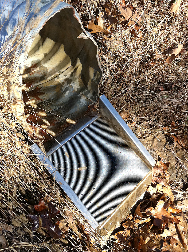
The intake can use an existing conduit – a road culvert in this case. Photo: Leif Kindberg, NCAT
Diversions and Intakes
The diversion and intake location is one of the most important parts of designing a low-maintenance micro-hydro system, and it depends on the geological, vegetation, and aquatic characteristics of your site. Diversions keep water continuously covering your hydro intake and can be designed on-site and at very low cost. Larger, more complex diversions such as dams may require a registered engineer to design them or at least approve your plans.
Intakes are available for purchase in a range of styles or may be fabricated on-site at very low costs. Some of the simplest diversions can be fabricated with a screen over the end of the penstock, a flume with a settling container (also called a forebay), a screen box, and other designs. These do-it-yourself designs may require frequent cleaning, depending on stream characteristics.
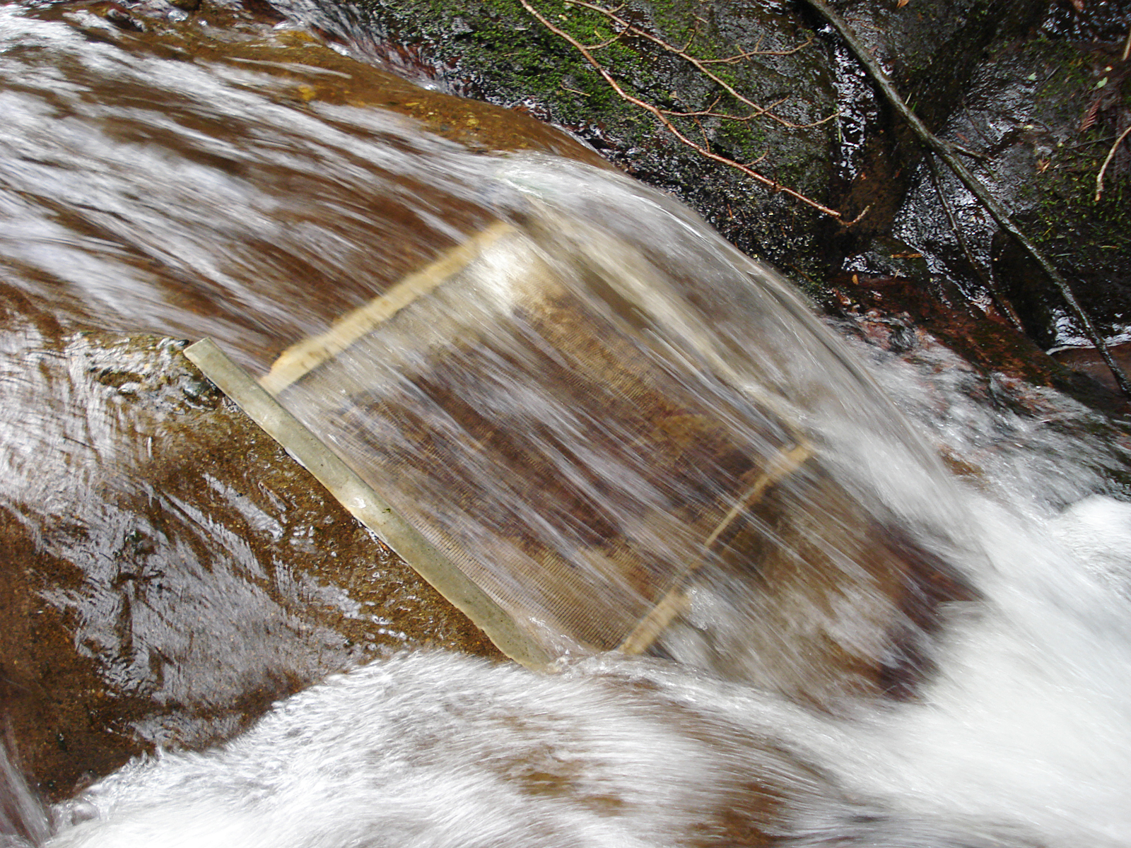
A Coanda-Effect screen works very well for many micro-hydro sites, and its low maintenance and durability is well worth its cost in most cases. Good diversion-construction information and intakes are available from a number of resources listed in the Further Resources section of this publication.
Keep in mind that the construction of dams and other types of permanent diversions will increase costs and may complicate the permitting process. Nonobstructive diversions that use natural characteristics of the stream, such as boulders, pools, and existing structures, to divert water into your intake may help the process go more smoothly.
Penstock
Almost all micro-hydro projects require piping (also called penstock), with the exception of some crossflow and propeller turbines. The most common types of pipe used for micro-hydro sites are white polyvinyl chloride (PVC), black polyethylene (PE), and high-density polyethylene (HDPE). These pipes come in several pressure ratings. When selecting pressure-rated pipe, be sure to allow an extra 40% above the expected static water pressure in the pipe (Ostermeier, 2008).
When water travels through a pipe, it creates friction. A properly designed hydro penstock can compensate for friction by increasing the pipe size and avoiding sharp changes in direction — although there is inherently a tradeoff in cost. Remember that cutting corners can reduce turbine performance and cause blowouts, leaks, and other problems. A reputable pipe dealer will be able to help you determine the appropriate pipe pressure rating and calculate friction losses based upon your hydro resource and site conditions. Pipes should be run as straight as possible, use long angles for going around obstacles, and steadily decline in elevation.
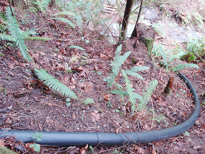
High-density polyethylene (HDPE) pipe is durable and manages bends better than rigid PVC or steel pipe. Photo: Leif Kindberg, NCAT
Beyond the pipe alone, a well-designed penstock in many projects will have air/vacuum release valves or stand pipes, unions, gate valves, thrust blocks, and supports. Also, installing a pressure gauge in the pipe above the lower shutoff valve will help you diagnose problems with the system later on. Design considerations for these components are discussed in many of the resources listed in the Further Resources section of this publication.
Power Generation and Storage
Mechanical energy from small turbines is converted to electricity by a generator, often similar to the one found in a car. The electricity can be delivered either as Alternating Current (AC) or rectified to Direct Current (DC). Most, but not all, farm equipment runs on AC, 110 or 220 volts, and 60 cycles (hertz). If you intend to be completely independent from the power grid, you will likely use a synchronous generator. AC systems in North America operate at a frequency of 60 hertz per second, and any variation from that will affect the operation of your equipment. In order to generate power at this frequency, the speed of the synchronous generator must be very constant, and a governor may be used to control the water flow and thus the turbine speed. If you have access to utility power, you can easily use an asynchronous generator with no governor, since it is self-regulating. In either case, the generator must run at its design speed, which means that some kind of speed increaser may be needed between the turbine and the generator. Most all-in-one small-hydro systems sold today have matched the turbine to the generator with a direct drive.
Another option is to generate direct current and either use it as-is or convert it to AC when needed through the use of an inverter. A battery bank with an inverter may be able to supply 2 to 5 kilowatts during peak loads, while the average power generated from the stream may be only 200 to 800 watts (Ministry of Agriculture and Lands, 2006). A DC-to-AC system has several advantages, especially in very small systems. The excess power generated by a DC system can easily be stored in batteries, thereby extending the system’s peak capacity.
Battery storage systems in hydro units generally work very well because the hydro generator is always putting some power back into the battery bank unless the water resource dries up. This means that deep-discharge condition — a common cause of battery failure — is very rare. The storage function does limit the size of a DC system because batteries become bulky and very costly as the system size increases.
Load Control and Governors
Hydropower systems need controllers that regulate the turbine speed and manage loads. Load controls monitor energy generation and demand and turn “dump load” resistors on and off to prevent damage to the turbine and other equipment. Battery-based systems require a charge controller to prevent them from overcharging the batteries. When the system is tied to the grid, the excess energy is sent there, or it can be sent to a dump load such as a baseboard or water heater. Off-grid AC systems without batteries for storage also use load controls to monitor voltage or frequency and correctly load the generator by turning on a dump load or mechanically deflecting water away from the runner. More information on load control and governors is available in the Further Resources section of this publication.
Power Lines
If your system is hydroelectric and the hydropower unit is any distance from the location where you need power, you will obviously need power lines. The longer the distance, the larger the wires that will be needed to avoid unreasonable power loss. This is especially true of 12-volt DC systems, which require very large wire to avoid excessive losses. Losses can be minimized in a number of ways:
- Using larger transmission wires
- Transmitting power less distance
- Increasing the voltage on the transmission wires
If, for example, the turbine is installed a long distance from the battery bank, the AC output can be rectified to a high DC voltage and then stepped back down to the correct voltage to charge the batteries. Experienced equipment dealers can help you design the system to reduce losses.
Economics
Any analysis of the economics of a micro-hydro system should include both the initial investment costs and the operation and maintenance costs. The initial investment cost calculation must include not only the turbine and generator, but also other variable expenses such as any pipes, power lines, buildings, dam construction, civil engineering work, permits, and legal work. One characteristic of many micro-hydro systems is that the up-front costs can be high, although the up-front and operating costs may be very competitive with generators, wind-electric systems, and solar-electric systems, as well as with conventional energy sources. Except for small maintenance costs, a micro-hydro system should provide “free” energy for 20 to 25 years or longer.
The up-front cost of a do-it-yourself hydroelectric system is generally in the range of $1,500 to $4,000 per kilowatt. The cost per kilowatt for smaller systems — those generating less than 5 kilowatts — will generally be relatively higher. Systems with high head and low flow generally cost less than low-head, high-flow systems of equal output because the components (e.g., intake, penstock, and turbine) will be smaller. However, the cost will vary greatly depending on any site work that may be needed and the system components used for the installation. If you hire a contractor to build some or all of your system, the cost will be higher than if you build it yourself. (See Figure 10.)
| Figure 10. Micro-Hydro System Costs: AC-Direct System Installed By a Contractor. | |||
| 100 Watt (flow rate of 63 gpm; head of 16 ft.) |
400 Watt (flow rate of 63 gpm; head of 80 ft.) |
3.5 Kilowatt (flow rate of 222 gpm; head of 165 ft.) |
|
| Component | |||
| Intake | $1,200 | $1,200 | $1,500 |
| Penstock | $2,000 | $2,00 | $4,000 |
| Turbine-generator | $2,300 | $1,500 | $2,500 |
| Controller | $350 | $350 | $650 |
| Transmission line | $300 | $400 | $1,500 |
| Powerhouse | $1,500 | $1,500 | $2,500 |
| Miscellaneous | $4,400 | $4,500 | $4,800 |
| Total cost of equipment | $12,050 | $11,450 | $17,450 |
| Installation cost | $3,000 | $3,000 | $4,000 |
| Cost/Watt | $150.50 | $36.13 | $6.13 |
| Total Cost | $15,050 | $14,450 | $21, 450 |
| Estimates provided by Ken Gardner, Gardner Engineering | |||
Micro-hydro system maintenance costs are generally among the lowest of any renewable-energy-producing technology. Maintenance usually involves clearing intake screens, unclogging nozzles, replacing deteriorated hoses and fittings, and replacing any equipment that may get damaged. If you estimate 5% per year, you are probably very close to the cost of maintaining your system for the next 20 or more years.
If your project has the potential to produce enough power to meet your energy requirements, the only other consideration is whether there are alternatives that could meet your needs at a lower cost. Compare various alternatives by calculating the energy-generation cost in dollars per kilowatt-hour over the equipment’s lifetime. Since the “fuel” is free for micro-hydro systems, you generally get the best value by running the system full time because the up-front costs are the same whether the turbine runs part time or full time. If the system will be shut down due to seasonal water variations, the unit cost of energy will be different.
Add up all the estimated costs to develop and maintain a micro-hydro system and divide the amount by the system’s capacity in watts. (See the “Cost Estimate Worksheet” appendix at the end of this publication.) This will give you the cost in dollars per watt. Then compare this to the cost of alternative power sources.
In the event that your site has access to conventional power and the water has no other uses, it may be difficult to justify a micro-hydro system in economic terms unless you are willing to take a very long-range view. There are a great many factors that will affect your analysis, and any such calculations must be done on a case-by-case basis. For those who are developing a site some distance from existing power lines, the cost of power-line extension should be considered. These costs may be in the range of $10,000 to $30,000 per mile depending upon the power company, making micro-hydro systems appear very attractive in remote locations.
Here are several questions to help you determine whether a micro-hydro system is best for you:
- How much energy do you need (e.g., kilowatt-hours and horsepower)?
- What are the options for generating that power where you need it (e.g., solar electric and diesel generator)?
- What is the cost of running power lines to your location?
- What are the up-front, operation, and maintenance costs of alternatives?
- Is your project eligible for tax credits or grants available from the state or federal government?
- How long do you expect to use power at this location, and would the hydropower system have market value if you wanted to sell the property where it is located?
- Is there a net metering law in your state that will allow you to get “credit” or sell your power through an agreement with your utility?
- How much of the installation and maintenance work can you do yourself?
The larger and more expensive a hydropower project becomes, the more valuable it is to conduct a detailed financial analysis. Commonly used financial analysis tools include net present value (NPV) and simple payback. Both tools will help you further assess whether a project is worth the investment.
The economics of each project are going to work out differently. When carefully designed, micro-hydro systems will generate years of hassle-free energy at costs that may be very competitive with retail rates available from your power company.
Financial Assistance
There are several potential sources of financial assistance available for micro-hydro projects at the state and federal level. The most comprehensive list of incentives for micro-hydro projects is available from the Database of State Incentives for Renewables and Efficiency (DSIRE). It is available online at www.dsireusa.org. This easy-to-use incentive database is searchable by state.
Rural Energy for America Program (REAP)
The Rural Energy for America Program (REAP) is a competitive grant and loan program administered by your state USDA Rural Development office. REAP provides grants and loan guarantees for micro-hydro projects, among other renewable-energy and energy-efficiency projects. Grants may be up to 25% of total eligible project costs. Small hydropower grants can range from $2,500 to $500,000. Loan guarantees may be up to 75% of total eligible project costs and can range from $5,000 to $25 million. It is also possible to receive both a grant and a loan guarantee for the same project — commonly known as a “combo.” Hydropower projects must have a rated power of 30 megawatts or less. For more information on the REAP program, contact your USDA Rural Development energy coordinator. You can find your energy coordinator at NCAT’s Directory of Energy Alternatives or by contacting your local Rural Development office.
Renewable Electricity Production Tax Credit (PTC)
The federal renewable-electricity-production tax credit (PTC) is a per-kilowatt-hour tax credit for electricity generated by qualified energy resources and sold to a utility. This tax credit is available only to incorporated businesses. The credit amount is 1.1 cents per kilowatt-hour.
State Grants and Tax Credits
Several states have tax credits and/or grants designed to encourage the development of renewable resources. In the case of a tax credit, you are generally allowed to deduct some percentage of the system’s total cost from your gross income. Be sure to run a quick calculation using your own figures to determine the program’s effect on the real cost of your system.
Conventional and Guaranteed Bank Loans
It is often possible to get a conventional loan from your bank or through U.S. Department of Agriculture or Small Business Administration guaranteed-loan programs. The interest you pay is usually tax deductible. If you do not have the taxable income to deduct the interest, there is little benefit in having deductible interest. Also, you may encounter some resistance from bank officials because they may be uncomfortable about loaning money for unfamiliar equipment. Do a thorough job of explaining the system to your loan officer and present any plans you have developed. If you encounter a situation in which your loan officer does not want to file the paperwork required for a guaranteed loan, ask the loan-guarantee agency (e.g., USDA Rural Development) for a list of banks in your area that it works with regularly.
There may be other incentives available from your state office of agriculture or energy.
Cautions and Suggestions for the Do-It-Yourselfer
You have learned about most of the necessary steps to develop your small hydro project — from calculating head and flow to applying and receiving your FERC permit. You are ready to purchase the equipment and begin installation. The following list of considerations can make installation much easier and prevent a lot of trouble at some future date.
In the final design stage, ensure that you take into account the following:
- Consider your streambed’s loading conditions. Silt and rocks coming down the stream, particularly during periods of high runoff, can clog the intake or even destroy the trash rack, intake, or penstock.
- Size the penstock to ensure that it is capable of handling the volume of flow you require. Any responsible pipe supplier can give you the correct size for the flow conditions expected and help you calculate any losses.
- Route the penstock, from intake to the turbine, to contain the minimum number of bends possible. Do not use 45-degree (or greater) elbows in the pipeline. Otherwise, there will be too much strain on the pipe and you will have excessive friction losses.
- Keep a downhill slope in the pipe route at all times (except for the initial siphon intake, if one is used) in order to avoid air locks and silt deposits.
- Use appropriately sized and placed thrust blocks. If the penstock will have a high velocity (above 5 feet per second), consult a professional for guidance.
- Size the pipe to maintain about a 5-feet-per-second line velocity in order to avoid excessive ice buildup in the pipe. If your line velocity is much less than this and you intend to install the system in an area where winters are severe, consider insulating or burying the line.
- Consider installing a water bypass before the turbine in case the water is needed for fire control.
- Locate the turbine and generator adjacent to the point of use whenever possible. This is important in order to keep line losses to a minimum by making electrical transmission lines as short as possible.
- Plan to install the system during relatively warm weather and not under freezing conditions if at all possible.
When buying or otherwise acquiring your equipment, you should keep the following in mind:
- Be sure you deal with a reputable supplier. There are always unprofessional salespeople and cheap, low-quality equipment. So buyer beware.
- Expect delays in getting quotes and deliveries from equipment suppliers since they are usually quite busy. At the same time, expect a high quality of service and thorough attention to your project needs.
- Buy good-quality pipe. Don’t buy seconds, especially for high-head systems.
- Use only gate valves. Other kinds of valving allow you to turn off the water too quickly, causing dangerous water-hammer effects.
- Ensure that you have a good trash-control system for the intake. A screen mesh should be used that has an opening smaller than the minimum diameter of the nozzle that leads into the turbine. This way, the only solid particles that can come down the pipe will be small enough to pass through the nozzle without clogging it.
During installation, remember the following:
- Be sure you follow the manufacturer’s or supplier’s instructions and suggestions.
- Slow down and do things properly. You are dealing with mechanical and electrical systems. They can cause you a lot of grief unless you treat them with respect.
- Watch for rocks, and be careful when placing PVC pipe.
- Use standard house-wiring procedures that comply with National Electric Code requirements for the electrical hook-up. Go to your local bookstore and pick up the appropriate electrical do-it-yourself book. Or if you feel unsure of your own capability to work with both DC and AC electricity, go to your local electrician for help.
- Once your system is operating, be very sure that when you have to close valves, you do it slowly to prevent water-hammer effects. Take a little time and screw the valves closed gradually. Closing valves too quickly can cause a shock wave (a high-pressure wave) to move through the water in the pipe. This will have a detrimental effect somewhere along the length of the pipe. The damage will vary depending on the length of the pipe and the velocity of the water at the point where the valve is closed. In many cases it will crack the pipe, and you will see a slow leak, or it could cause a serious rupture in the pipeline.
Installing a micro-hydro system is generally something farmers can do safely if they take all necessary safety precautions into consideration. However, installing one of these systems is a complex task, combining elements of electrical work, high-pressure plumbing, and heavy construction. Be very cautious when taking the do-it-yourself approach to a micro-hydro project.
Conclusion
Micro-hydro systems can supply electrical energy at a cost that often is less than running a generator or extending power lines to a property. Micro-hydro systems should be considered similar to other structural farm improvements that have many years of operating life. They are a long-term investment, but they will provide many years of reliable power when they are designed correctly and properly maintained.
Acknowledgements
Thank you to authors Ron Alward, Sherry Eisenbart and John Vokman, as well as illustrator Hans Haumberger, for their 1979 NCAT publication Micro-Hyrdro Power: Reviewing an Old Concept.
Further Resources
Equipment Manufacturers and Suppliers
Alternative Power & Machine
4040 Highland Ave.
Grants Pass, OR 97526
Phone: 541-476-8916
Sales email: altpower@grantspass.com
Product inquiries email: altpower@grantspass.com
This company builds and sells complete micro-hydro systems.
AquaScreen Enterprises
2617 Nassau Circle
Modesto, CA 95355
Phone: 209-491-0371
Fax: 209-544-2378
Email: aquascreen@jbmj.com
This company manufactures screens for hydro intakes.
Canyon Hydro
5500 Blue Heron Lane
Deming, WA 98244
Phone: 360-592-5552
Email: info@canyonhydro.com
This company builds complete systems up to 25 MW.
Dependable Turbines
17930 Roan Place
Surrey, BC
Canada V3S 5K1
Phone: 604-576-3175
Email: sales@dtlhydro.com
This company builds complete systems to meet specifications in the capacity range of 1 kW to 10,000 kW.
EcoInnovation
This company provides complete systems and parts for a variety of system configurations.
Energy Systems and Design
P.O. Box 4557
Sussex, NB Canada E4E 5L7
Phone: 506-433-3151
This company provides complete low-head systems.
Harris Hydro
Phone: 707-986-7771
Email: delejo@humboldt.ne
This company provides complete systems for a variety of heads and flows.
Hydro Induction Power
3530 Briceland Thorn Road
Redway, CA 95560
Phone: 707-923-3507
Email: info@hipowerhydro.com
This company provides complete systems for a variety of heads and flows.
Hydroscreen, LLC
2390 Forest Street
Denver, CO 80207-3261
Phone: 800-567-4916
This company provides high-quality, low-maintenance intake products for small hydro projects.
Low Impact Hydropower Institute
The Low Impact Hydropower Institute (LIHI) is a non-profit 501(c)(3) organization that provides standards designed to reduce the impacts of hydropower generation through the certification of hydropower projects that have avoided or reduced their environmental impacts pursuant to LIHI’s criteria.
Norris Screen Manufacturing
21405 Gov. GC Peery Hwy
Tazewell, VA 24651
Phone: 276-988-8901
Fax: 276-988-8909
Email: norris@elginindustries.com
This company designs screen products for hydro intakes.
PowerPal
2-416 Dallas Road
Victoria, BC
Canada V8V 1A9
Phone: 250-361-4348
Email: info@powerpal.com
This company builds complete systems in the capacity range of 200W to 20kW.
Regulatory Agencies and Associations
Federal Energy Regulatory Commission (FERC)
Public Reference Room
888 1st St., N.E.
Washington, DC 20426
Small Hydro Hotline: 866-914-2849
Phone: 202-208-1371
Fax: 202-208-2320
Email: smallhydro@ferc.gov
FERC provides licensing exemptions and guidance on small and low-impact hydropower projects.
National Association of State Energy Officials (NASEO)
1414 Prince St., Suite 200
Alexandria, VA 22314
Phone: 703-299-8800
Fax: 703-299-6208
Email: info@naseo.org
NASEO provides current contact information for state energy offices, including links to their websites.
National Hydropower Association (NHA)
One Massachusetts Ave., N.W., Suite 850
Washington, DC 20001
Phone: 202-682-1700
Fax: 202-682-9478
Email: info@hydro.org
NHA seeks to secure hydropower’s place as an emissions-free, renewable, and reliable energy source.
Solar Energy International (SEI)
P.O. Box 715
Carbondale, CO 81623
Phone: 970-963-8855
Fax: 970-963-8866
Email: sei@solarenergy.org
SEI offers workshops on how to design fully functional micro-hydro systems.
Useful Websites
Idaho National Laboratory Hydropower Page
This website provides an overview of hydropower in the U.S. and a GIS application to locate and evaluate hydropower resources in naturally occurring streams.
Build it Solar
This website provides plans and resources for small-scale hydropower.
Database of State Incentives for Renewable Energy (DSIRE)
This database features information on state, utility, and local government financial and regulatory incentives, as well as programs and policies designed to promote renewable-energy technologies.
Home Power Magazine
P.O. Box 520
Ashland, OR 97520
Phone: 800-707-6585
Email: hp@homepower.org
This is a do-it-yourself magazine with articles discussing many aspects of designing a micro-hydro system. The following are some selected helpful articles:
- “Pipeline: Hydro-Electric Penstock Design,” J. Ostermeier, (No. 125) p. 56-62, June/July 2008
- “Intro to Hydropower: Part 1: Systems Overview,” D. New, (No. 103) p. 14-20, October/November 2004
- “Intro to Hydropower, Part 2: Measuring Head and Flow,” D. New (No. 104), p. 42-47, December 2004/January 2005
- “Intro to Hydropower, Part 3: Power, Efficiency, Transmission and Equipment Selection,” D. New, (No. 105) p. 30-35, February/March 2005
- “Hydro-Electric Turbine Buyers Guide,” K. Gardner and I. Woofenden, (No. 136) p. 100-108, April/May 2010
- “Hydro Design Considerations,” Ian Woofenden, (No. 132) p. 78-84, August/September 2009
- “From Water to Wire: Building a Microhydro System,” P. Talbot, (No. 76) p. 8-22, April/May 2000
- “Induction Motors for Small-Scale Hydro,” B. Haveland, (No. 71) p. 36-44, June/July 1999
- “A Microhydro Learning Experience,” L. Woofenden et al., (No. 76) p. 64-71, April/May 2000
Microhydro
This website features a discussion group and literature on small-scale hydropower.
U.S. Department of Energy Wind & Water Power Program
This website provides resources and technical publications on various hydro technologies.
Why Hydro Power?
This website is sponsored by Canyon Hydro; it discusses hydropower and provides resources and information on small- and medium-scale hydropower.
Free Software on Micro-Hydro Power Systems
RETScreen® International is a standardized software program for analyzing renewable-energy projects that can help you determine whether a micro-hydro power system is a good investment. The software uses spreadsheets and supporting databases to aid your evaluation. It comes with a comprehensive manual. You can download the software and manual free of charge at www.retscreen.net. Call Natural Resources Canada at 450-652-4621; or fax your request to 450-652-5177.
Books, Pamphlets, and Reports
Microhydro: Clean Power from Water. 2003. Scott Davis. New Society Publishers, Gabriola Island, BC, Canada.
Micro-Hydro Design Manual: A Guide to Small-Scale Hydropower Schemes. 1993. A. Harvey et al. Intermediate Technology Publications, London.
This 228-page manual covers design, energy surveys, operation and maintenance, commissioning, electrical power, induction generators, electronic controllers, and management.
Micro-Hydro Pelton Turbine Manual. 1999. J.Thake. Intermediate Technology Development Group, London. ISBN 185339-460-2.
This 320-page book provides information about manufacturing Pelton turbines.
Micro Hydro Power Sourcebook. 1986. A. Inversin. National Rural Electric Cooperative Association (NRECA).
This manual thoroughly describes all aspects of micro-hydro system design and installation in a developing-country context, but it contains information that is applicable anywhere.
Mini-Hydropower. 1997. J. Tong (ed.). John Wiley and Sons, Ltd., Hoboken, NJ.
Motors as Generators for Micro-Hydro Power. 1994. N. Smith. Intermediate Technology Development Group, London. Available from Practical Action in the United Kingdom, or Amazon.com in the United States.
This 84-page guide discusses the use of induction motors for electricity generation.
Pumps as Turbines: A User’s Guide. 1995. A. Williams. Intermediate Technology Development Group, London, 1995. Available from Practical Action in the United Kingdom, or Amazon.com in the United States.
This is a practical book on the use of standard water pumps as water turbines.
Solar Living Sourcebook. 2007. J. Schaeffer (ed.). Chelsea Green Publishing Company, White River Junction, VT.
This book contains a section on hydro systems and lists micro turbines available by mail order from Real Goods.
Water Current Turbines: A Field Workers Guide. 1986. P. Garman. Intermediate Technology Development Group, London.
This 100-page guide describes experiences with current turbines.
References
Alward, Ron, Sherry Eisenbart, and John Vokman. 1979. Micro-Hydro Power: Reviewing an Old Concept. National Center for Appropriate Technology (NCAT), Butte, MT.
Davis, Scott. 2003. Micro-Hydro: Clean Power from Water. New Society Publishers, Gabriola Island, BC, Canada.
McKinney, J.D., B. Bradley, J. Dodds, T.B. McLaughlin, C.L. Miller, G.L. Sommers, B.N. Rinehart, and C.C. Warnick. 1983. Microhydropower Handbook. In two volumes. EG&G Idaho, Inc.,
Idaho Falls, ID.
Ministry of Agriculture and Lands, British Columbia. 2006. On-Farm Hydroelectric Generation. Abbotsford, BC, Canada.
Murray, Shana. 2010. Small/Low-Impact Hydro Webinar (Identifying number: AD09-9-000). Federal Energy Regulatory Commission, Washington, DC
Natural Resources Canada. 2004. Micro-Hydropower Systems: A Buyer’s Guide. Ottawa, ON, Canada.
New, D. 2004. Intro to HydroPower, Part 2: Measuring Head & Flow. Home Power 104. December 2004 and January 2005. p. 42-7.
Ostermeier, Jerry. 2008. Pipeline: Hydro-Electric Penstock Design. Home Power Magazine. June and July. p. 56-62.
Woofenden, Ian and Ken Gardner. 2010. Micro-Hydro Training – Micro-Hydro Design & Installation. Training held on Guemes Island, Washington. Solar Energy International, Carbondale, CO.
Appendix: Cost Estimate Worksheet
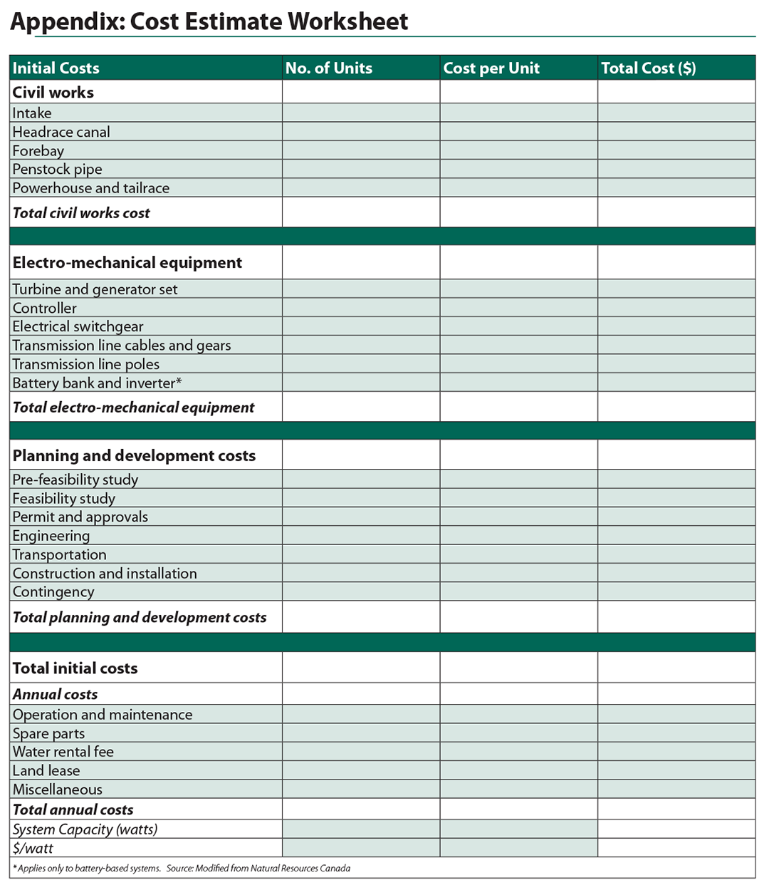
Micro-Hydro Power: A Beginners Guide to Design and Installation
By Leif Kindberg
NCAT Energy Specialist
IP383
This publication is produced by the National Center for Appropriate Technology through the ATTRA Sustainable Agriculture program, under a cooperative agreement with USDA Rural Development. ATTRA.NCAT.ORG.