Maintaining Irrigation Pumps, Motors, and Engines
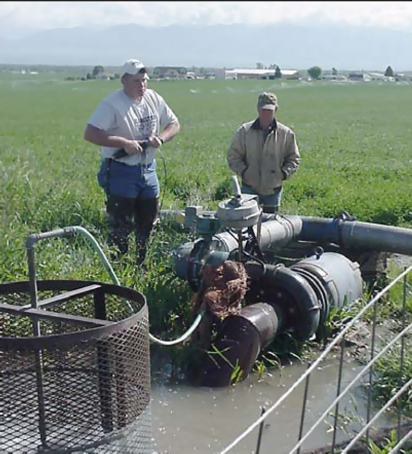
Photo: NCAT
By Mike Morris and Vicki Lynne, NCAT Agriculture Specialists
Abstract
This publication explains how to maintain irrigation pumps, motors, and engines for peak efficiency. The publication includes descriptions and diagrams of recommended installations, checklists for maintenance tasks, and a troubleshooting guide. Each system component is treated separately and maintenance tasks are broken down by how frequently they need to be done. References and resource listings follow the narrative.
Contents
Introduction
Recommended Installations
Pumping Plant Maintenance
Troubleshooting
References
Introduction
Efficient irrigation begins with properly installed and maintained pumps, motors, and engines. Equipment problems and management problems tend to go hand in hand. Equipment that is badly designed or poorly maintained reduces the irrigator’s degree of control over the way water is applied. Problems like patchy water distribution and inadequate pressure make it impossible to maintain correct soil moisture levels, leading to crop stress, reduced yields, wasted water, runoff, soil erosion, and many other problems.
Recommended Installations
Centrifugal Pumping Plant Installation with Electric Motor
The term “pumping plant” refers to the irrigation pump and motor or engine, considered together. If you have an older system, the pumping plant might look like Fig. 1, Poor, on the discharge side. The next time you rebuild the pump, replace the fittings so that your system will look like Fig. 1, Ideal.
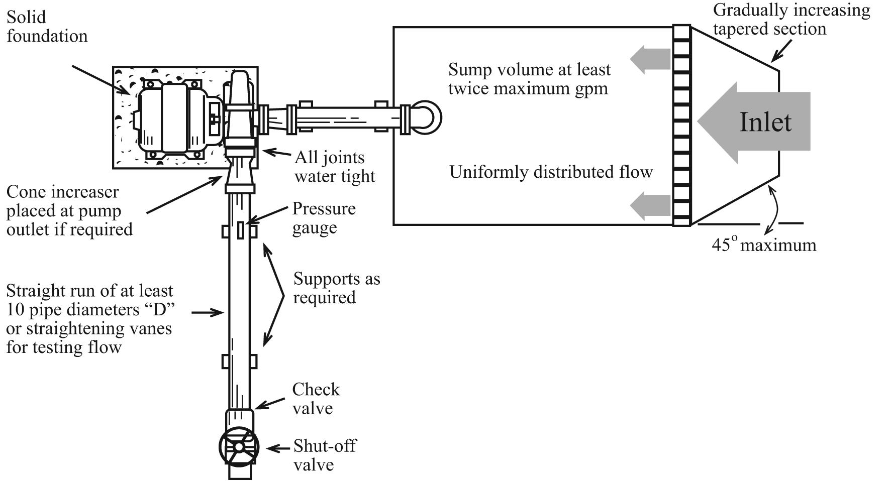
Figure 1. Ideal and Poor Installations

Adapted from: Energy Efficient Pumping Standards, Utah Power & Light Company
An ideal installation should also have:
- A discharge concentric expansion instead of an abrupt change in pipe diameter, to minimize head loss, turbulence, and air pockets.
- A discharge valve the same diameter as the mainline.
Fig. 2 shows what your pumping plant should look like when pumping from a surface source such as a river or canal. The pumping plant should also have:
Figure 2. Recommended Pump Installations, Top and Side Views
Top View
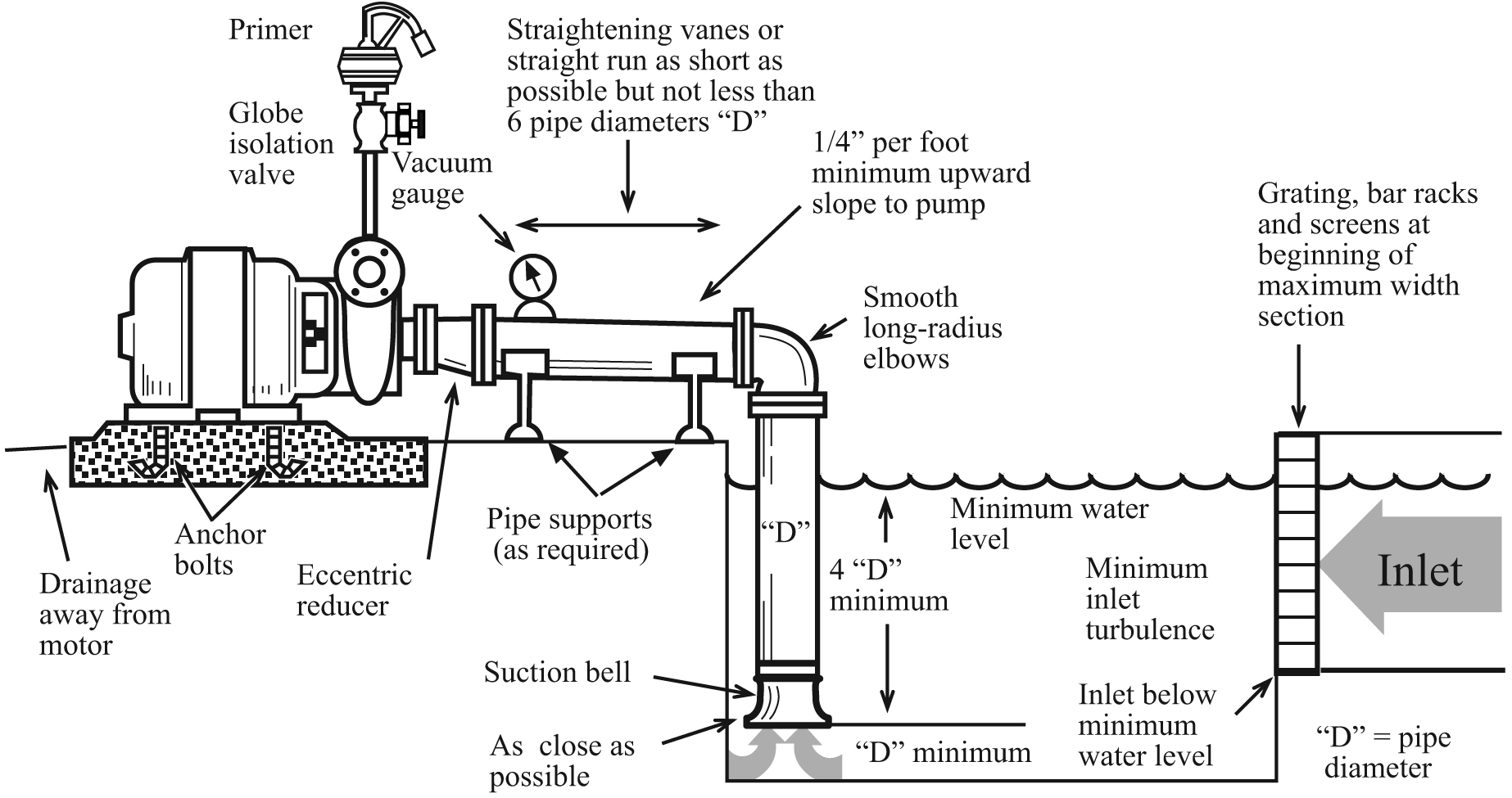
Side View
Adapted from: Energy Efficient Pumping Standards, Utah Power & Light Company
On the Suction Side of Pump:
- A well designed and screened sump that keeps trash away.
- Suction line joints that are airtight under a vacuum.
- No high spots where air can collect.
- A suction line water velocity of five feet per second (fps) or less; two to three fps is best.
- A suction entrance at least two pipe bell diameters from sump inlet.
- A suction lift (vertical distance from water surface to pump impeller) less than 15 to 20 feet.
- An eccentric reducer to keep air from becoming trapped in the reducer fitting.
- A vacuum gauge to indicate whether the primer is pulling a vacuum or just moving air through the pump.
On the Discharge Side of Pump:
- A valve size that is the same diameter as the mainline
- A non-slam check valve to prevent back spin when shutting off the pump.
- An air relief device when a buried mainline is used.
- A discharge line water velocity of less than seven fps. Five fps is best.
- An energy efficient 1800 rpm motor with a 15 percent safety factor.
- A simple shade over the motor.
Turbine Pump Installation
Refer to the left half of Fig. 3 for a properly installed turbine pump in a well; many of these same principles apply to turbine pumps in sumps. The properly constructed well should also:
- Be at least six inches in diameter larger than the outside diameter of the well casing when a gravel pack is required.
- Have horizontal well screen slots that continue below the pumping water level. The openings should hold back at least 85 percent of the surrounding material.
Figure 3. Deep Well Turbine Pump
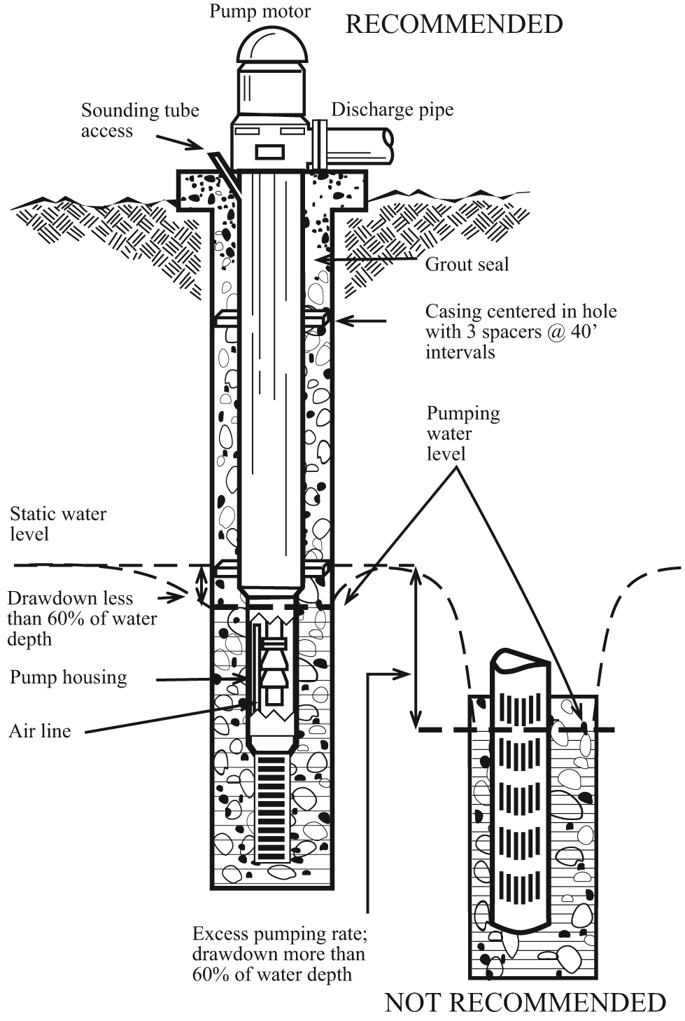
Adapted from: Energy Efficient Pumping Standards, Utah Power & Light Company
The poorly constructed well in the lower right half of Fig. 3 shows a well casing that is not centered in the well. Vertical slotted pipe perforations are above the minimum water level, creating cascading water.
Control Panel for Electric Motors
The importance of a properly installed control panel cannot be overemphasized for personal safety and for protecting your investment in your pump and motor.
Your control panel should:
- Have a shade over it to keep thermal breakers cool.
- Be mounted on secure poles or foundation.
- Have any missing knockout plugs and other holes in the starting switch box replaced and screened or puttied against rodents, insects, and dirt.
- Have a small hole (3/16-inch diameter) in the bottom of the panel to allow moisture to drain.
Your control panel should include the following controls at a minimum:
- Circuit breaker(s) for overload currents.
- Lightning arrester.
- Surge protector.
- Phase failure relay, to protect the motor from phase reversal or failure and from low voltage.
- A pressure switch to shut off the motor if pumping pressure drops to undesirable levels.
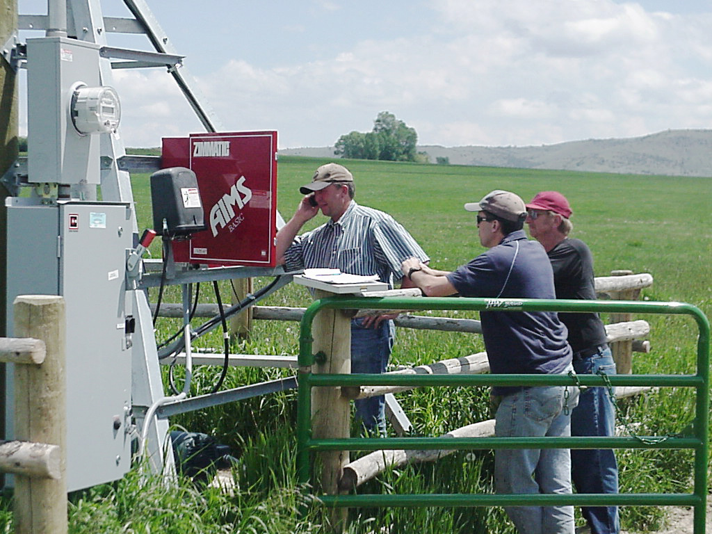
Photo: NCAT
Pumping Plant Maintenance
Every irrigation system needs regular maintenance in order to run efficiently and reliably. Poorly maintained systems waste energy and money, and are prone to breakdowns that cause crop losses and yield reductions.
Caution: The recommendations below are not comprehensive and may not be correct for all systems. Consult your owner’s manual for recommended maintenance procedures and always follow the manufacturer’s instructions if they differ from the ones in this guidebook.
Electric Motor Maintenance
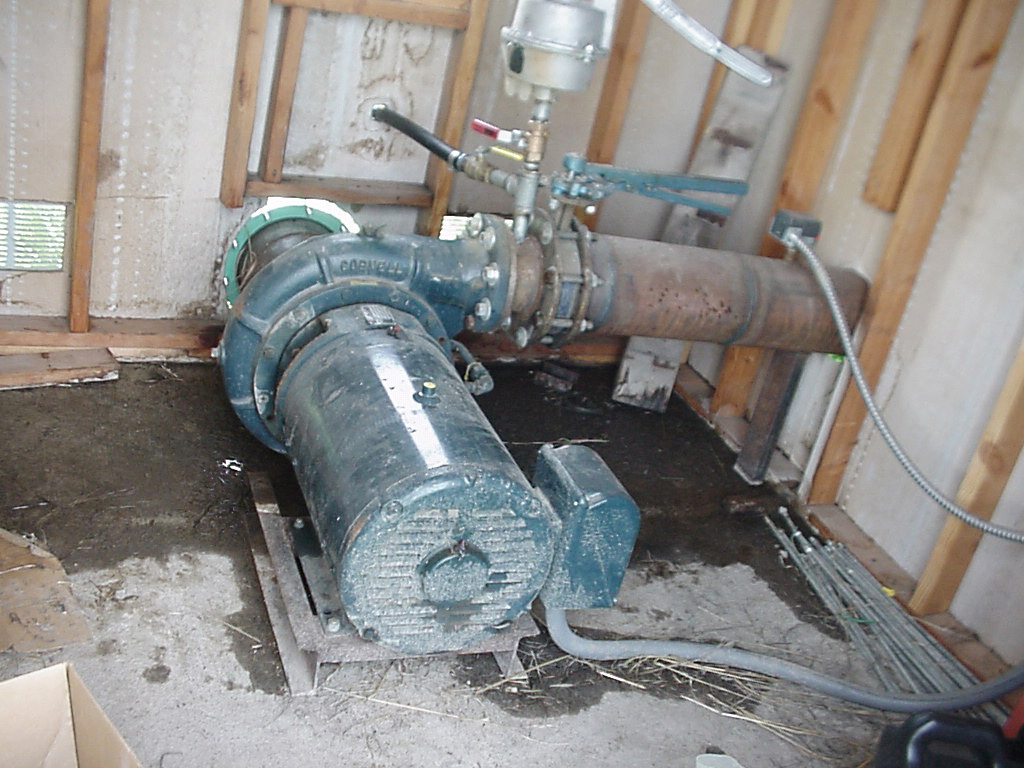
Photo: NCAT
General
Make a habit of checking that the motor is securely bolted to its platform. Mounting bolts can vibrate loose. Check to see that rotating parts aren’t rubbing on stationary parts of the motor, causing damage to the motor.
Remember that an electric motor is an air-cooled piece of equipment and needs all the ventilation it can get. Excessive heat is a main cause of reduced motor life.
Motors also like to be dry. Keep motor windings dry by keeping pump packing in good condition. Even if windings are protected from moisture, minerals in the pumped water can attach to the windings and cause early failure. Motors that operate at 3600 rpm experience twice as much wear as motors operating at 1800 rpm. Regular maintenance is especially critical for 3600 rpm motors and pumps.
Maintenance Tasks
At season startup:
- Remove tape on all openings and clean out rodents, insects, or debris.
- Locate the motor drain hole on the base or support for the base, and clean it out so water won’t be trapped and held directly under the air intake.
- Change oil in reduced voltage starters, using an oil recommended by the manufacturer. Be sure to clean the oil pan before refilling.
- Use vacuum suction or air pressure to remove dust and debris from moving parts of the motor. (Don’t exceed 50 psi of air pressure.)
Periodically:
- Clean grass or debris from air ventilation openings on the motor and from around the motor to allow a full flow of cooling air.
- Check screens on motor ventilation openings. Replace with machine cloth (¼-inch mesh) as necessary.
At end of season shutdown:
- Cover the motor with a breathable water-resistant tarp.
Motor Electrical System
Wide temperature fluctuations during the year can cause electrical connections (especially in aluminum wire) to expand and contract, loosening connectors. Loose electrical connections cause heat buildup and arcing at electrical terminals. The voltage drop across loose connections will cause the motor to operate at less than its rated voltage, increasing internal motor temperature. Increased heat will break down motor winding insulation, resulting in electrical shorts and motor failures. A loose or broken connection can also unbalance the phases of three-phase power and damage the motor windings.
Caution: Before conducting these tasks, be sure power is off at the utility disconnect switch. It may be necessary to have the utility company shut the power off.
Maintenance Tasks
At season startup:
- Inspect insulation of motor windings. If the windings are excessively grease-covered, consult your motor repair shop for direction.
- Check all safety switches according to the manufacturer’s directions.
Twice a year:
- Check electrical connections from meter loop to motor for corrosion and clean if necessary. Coat the wiring (especially aluminum) and connectors with an antioxidant that meets electrical code requirements.
- Check electrical connections from the meter loop to the motor for tightness. Tighten and re-tape if necessary.
- Replace overheated connections or wires with new material. Overheated connections will show heat damage such as burnt insulation on wires.
Motor Bearings
Lubricate the motor according to the manufacturer’s instructions. Intervals between lubrication will vary with motor speed, power draw, load, ambient temperatures, exposure to moisture, and seasonal or continuous operation. Electric motors should not be greased daily. Bearings can be ruined by either over- or under-greasing.
Fill a grease gun with electric motor bearing grease and label it so it won’t be confused with other types of lubricating grease.
Caution: Lubrication instructions in owner’s manuals should be followed if they differ from these. Newer motors may have sealed bearings that cannot be lubricated.
Table 1. Recommended Re-greasing Periods for Motors
Horsepower Range |
|||
|
Type of Service |
1-9 | 10-40 | 50-150 |
|
Normal Duty |
8 mos. | 6 mos. | 4 mos. |
| Heavy Duty (24-hour day) |
4 mos. | 3 mos. |
2 mos. |
Maintenance Tasks
Change the grease at recommended intervals to remove any accumulated moisture:
- Remove the bottom relief plug and clean hardened grease out of passageway.
- Using a grease gun, fill the housing with approved high temperature electric motor bearing grease (refer to the manufacturer’s manual for API number of grease) until old grease is expelled.
Caution: If old grease is not expelled as the new grease is pumped in, stop adding grease and have your motor checked by a qualified repair person. Adding new grease without old grease being removed could blow the seals and push grease into the motor windings, causing the motor to overheat and reducing its service life. Do not over-grease your motor.
- Run motor until all surplus grease is thrown out through the bottom grease port (may require 5 to 10 minutes).
- Shut off the motor and use a screwdriver or similar device to remove a small amount of grease from the grease port to allow for grease expansion during full load operation.
- Replace grease plug.
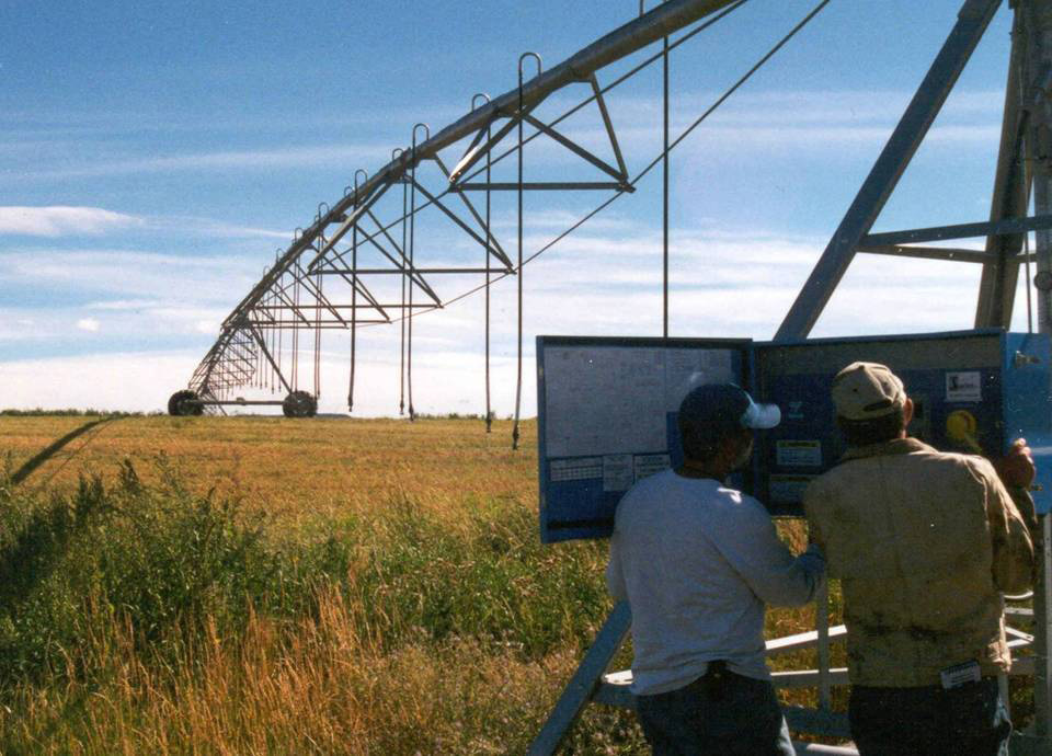
Photo: NCAT
Control Panel Maintenance
Control Panel Safety Precautions
Never use the main disconnect to start or stop your motor. It is not intended for this purpose. Using the main disconnect to start and stop the motor will cause excessive wear of the contacts and arcing can occur. Use the start and stop button.
If the overhead lines to your control panel’s service are obstructed by tree branches or other items, have the utility company clear the lines.
Have an electrician inspect your panel to ensure that:
- Control circuits are protected with the correct size and type of fuse.
- Lightning arresters are properly installed on the meter and motor side of the buss and breaker. They should also be mounted in a secure box to protect you if they blow up.
- The service panel is properly grounded, independently of the pumping plant.
- Service head grommets are in place and in good condition.
General Maintenance
Have your electrician or pump maintenance person do a Megger check on the control panel, motor, conduits, and other electrical connections. The Megger device applies a small amount of voltage to an electrical component and measures the electrical resistance. A Megger test can also detect potentially harmful moisture in windings.
Any time the main disconnect switch has been left open or off, operate it several times before leaving it closed or on. Copper oxide can form in a few hours and result in poor contact and overheating. Any type of corrosion can cause poor contact, poor grounding, and direct or high-resistance shorts.
Caution: After opening the control panel but before touching the controls inside, use a voltmeter to be sure that the incoming power is disconnected or turned off. If necessary, have your utility disconnect the power. If you have any doubts about the safety of your control panel, WALK AWAY AND CALL A QUALIFIED ELECTRICIAN. Even a current of 15 milliamps (one milliamp is one one-thousandth of an amp) can cause serious injury or death. Always play it safe!
Maintenance Tasks
At season startup:
- Replace fuses after checking to see that they aren’t blown. Never use oversized fuses.
- Operate disconnect switch slowly to check for alignment of blades and clips.
- Open and close the disconnect switch several times to clean oxide from contact points.
- Clean contacts of all dust and dirt. Clean copper contacts with very fine sandpaper or a fine file. Replace badly pitted or burned contacts. Never file silver or silver-plated contacts. Leave contacts clean and dry so dust won’t collect.
- If easily accessible, check magnetic starter switch contact points.
- Periodically clean out debris, rodent droppings, and nests and insects. Make sure drain hole is open.
At end of season shutdown:
- Ensure that switches are in the off or open position. Lock the panel in the off position and remove the fuses to prevent accidental startup and vandalism. Removing fuses will also prevent corrosion.
- Protect exposed control boxes against moisture and dust with a waterproof tarp.
Engine Maintenance — Diesel, Gasoline, Liquid Propane Gas (LPG), and Natural Gas
Make a habit of checking that the engine is securely bolted to its platform; mounting bolts can vibrate loose. Regularly check coolant, oil levels, fuel, and fan belts. If coolant or oil is down, check lines for leakage. On diesel engines, check injectors and fuel lines for leaks.
Engine power is affected by altitude and air temperature. Derate engine power output by 3.5 percent for every 1,000-foot increase in altitude over 500 feet above sea level. Derate output by 1 percent for each 10-degree increase in air temperature above 85 degrees F.
Engine Startup (Beginning of Season)
Maintenance Tasks
- Remove tape on all engine openings and the distributor cap, and tighten belts.
- Charge batteries and connect them.
- Open fuel tank shutoff valve.
- Before starting the engine, override safety switches that protect against low water pressure, loss of oil pressure, and overheating. After engine has reached operating speed, activate the safety switches.
- Run the engine for 10 minutes, then turn it off and check oil and coolant levels.
- Check engine and pump for any leaks caused by drying gaskets.
Engine Air System
Always replace disposable air filters with new ones. Cleaning can distort the filter and allow more dirt to enter.
Maintenance Tasks
- At season startup, clean and refill the filter bath in oil-bath air cleaners and reassemble the air cleaner.
- Periodically brush blockage off the screen if the air induction system is equipped with a pre-screener.
- Change the air filter when the service indicator signals that it’s time to change it:
—Turn off engine before changing air filter.
—Wipe the outside of the cover and housing with a damp cloth and remove the cover.
—If cover is dented or warped, replace it.
—Use extreme care when removing the filter to prevent dirt from falling into the intake duct. Use a clean damp cloth to wipe inside of filter housing.
—Install new air filter.
Engine Electrical System
If you have a natural gas engine, be aware that natural gas has a higher-octane value than automotive gasoline. You can increase engine efficiency and reduce fuel consumption by setting the ignition timing to take advantage of the higher octane. Consult the engine manufacturer for recommendations on how to do this.
Maintenance Tasks
At season startup:
- Inspect breaker points for wear and replace if needed.
- Set the gap or dwell angle and lubricate the rotor.
- Check timing and adjust if necessary.
- Clean all connecting terminals; cover with protectors.
- Spray silicone on electrically operated safety switches and ignition system to prevent corrosion.
Twice a year:
- In engines that have them, clean and re-gap spark plugs or replace with plugs in the recommended heat range.
- Check all terminals and electrical connections for tightness and corrosion, and spray with corrosion inhibitor (NOT grease).
- Remove the distributor cap and lubricate governor weights with silicone (NOT oil).
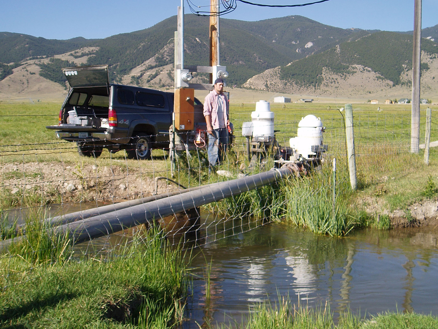
Photo: NCAT
Engine Oil and Lubrication
Have a sample of engine oil analyzed for contaminants, which signal abnormal wear. Intervals between analyses will depend on the engine, and analysis may be cost-effective only for larger engines. Equipment dealers should know where the oil can be analyzed and how often this should be done.
Use only the oil recommended by the manufacturer. Tag each engine with a label identifying the proper oil.
Maintenance Tasks
Twice a year:
- If the engine was not protected during shutdown, or if the oil has not been changed within the last year, change the crankcase oil and oil filter.
- Lubricate all engine accessories such as the driveshaft and U-joints.
Engine Fuel and Coolant
Maintenance Tasks
- Twice a year remove and clean or replace the fuel filter.
- Periodically check that fuel tank cap and oil filter cap are on tight and that gaskets aren’t cracked.
- Periodically check that the fluid level and degree of coolant protection are adequate. Check that the radiator cap is on tight and that gaskets aren’t cracked.
Engine Shutdown (End of Season)
Maintenance Tasks
- Drain all fuel from the tank and lines and shut off the fuel valve. If LP gas is used, drain vaporizer-regulator. (Drain both fuel and water lines.)
- Remove spark plugs. Pour a tablespoon of clean motor oil into each spark plug hole. Position spark plug wire away from cylinder opening and rotate crankshaft by hand to lubricate piston and rings. Replace spark plug.
- Seal the distributor cap with duct tape where the cap joins the distributor housing.
- Seal all the openings in the engine with duct tape, including air cleaner inlet, exhaust outlet, and crankcase breather tube.
- If the engine coolant is water, drain and refill the cooling system with water, a rust inhibitor, and antifreeze.
- Remove tension from belts.
- Remove and store batteries in a cool but not freezing location. Do not store batteries directly on concrete.
- If engine is outside, cover with a water-resistant tarp.
Centrifugal Pump Maintenance
Centrifugal Pump Startup (Beginning of Season)
Maintenance Tasks
- Using new gaskets and pipe-dope, reconnect to the pump any piping removed during shutdown.
- Re-install the primer and priming valve if they were removed during shutdown.
- Check that the pump shaft turns freely and is free of foreign objects. Applying power could break the impeller if it’s rusted to the case.
- Check the pump for leaks caused by drying gaskets.
- Check intake and discharge piping for proper support and make sure the pump is securely bolted to the platform.
- Clean the drain hole on the underside of the pump.
Figure 4. Centrifugal Pump and Motor
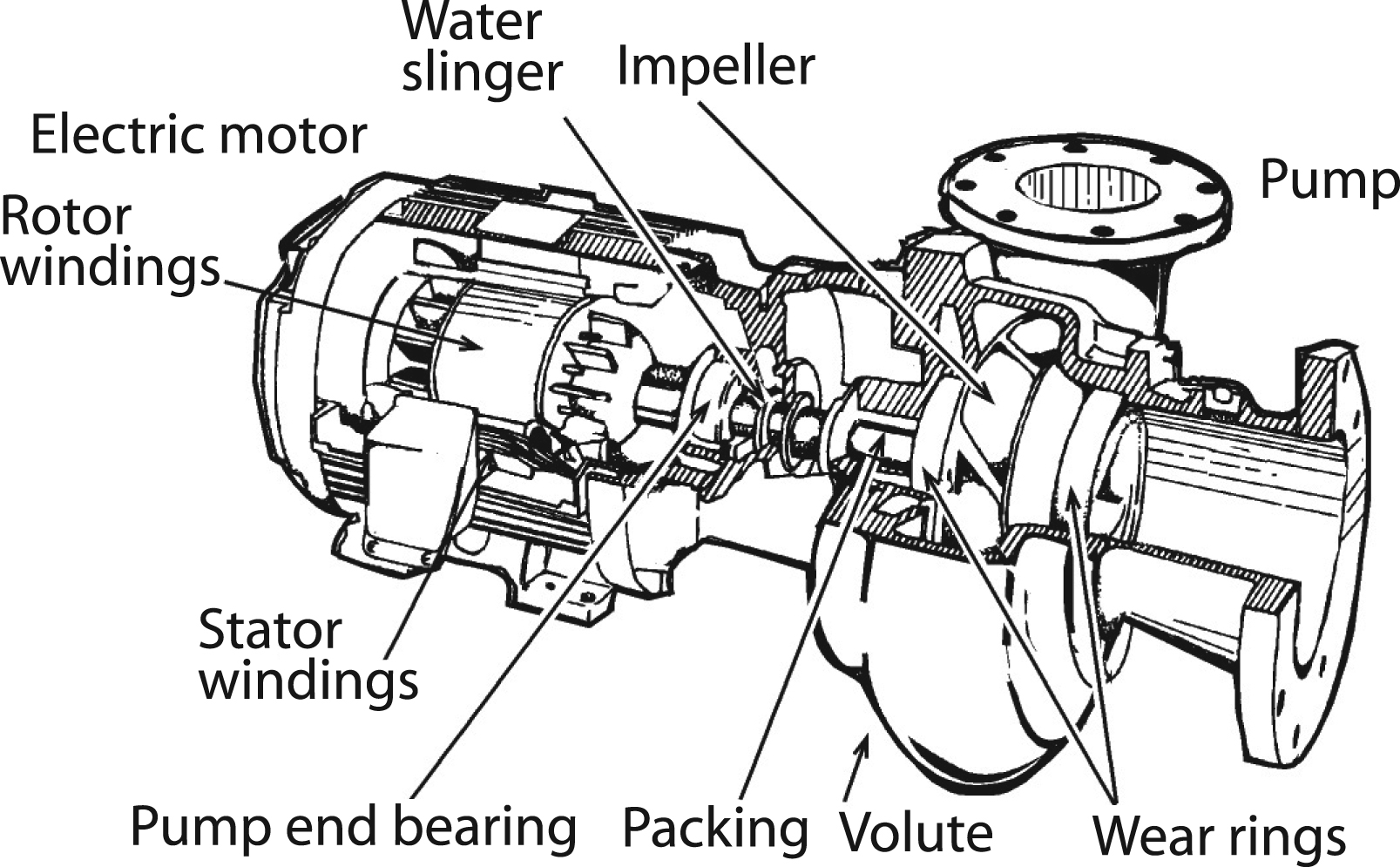
Adapted from: Energy Efficient Pumping Standards, Utah Power & Light Company
General
To avoid water leaks, make sure that all gaskets are the correct ones for the coupling or flange. Eliminate air leaks in your pump’s suction line by coating threaded connections with pipe cement or white lead and drawing them tight. Also examine suction line welds for cracks, which will allow air leaks.
Choosing Gaskets
Using a gasket in a coupling that it was not made for is a common cause of leaky gaskets. Get the right gasket and the right kind of gasket for the fitting.
Flat gaskets: Most are made of neoprene and are used on flanged, bolt-together fittings. They are usually not expensive. They normally fail by “creeping” out of their fitting. Look for new neoprene gaskets that contain a cotton backing sandwiched in the gasket to reduce the creeping action.
Shaped gaskets: The three most common materials are styrene-butadiene (SBR), ethylene-propylene (EPDM), and polyethylene (poly). SBR and EPDM have much better resistance to cracking, abrasion, ozone, and weathering resistance than poly gaskets. They are more expensive than poly but will last longer. When buying shaped gaskets, look for gaskets that are dull; this indicates that little or no plasticizer has been added to the gasket. Plasticizers significantly reduce gasket life.
Photo: NCAT
If your pump isn’t delivering water, verify that the pump shaft is turning in the direction of the arrow on the pump casing. As viewed from the motor end, the rotation is usually clockwise, but check the startup instructions that came with the pump. On three-phase motors, swap any two power leads to change rotation. It is recommended that a qualified electrician perform this task.
If the pump doesn’t prime, check for air leaks on discharge valves. Many all-metal gate-type valves won’t seal properly to create a vacuum. Sand or other debris lodged between the rubber flap and the valve seat will prevent check valves from sealing and forming a tight joint. See if the rubber face is cracked or chipped and not seating. Replace the gate valve or check valve. Check connections between pump and primer. On a hand primer, if grass or other debris is lodged in the check valve, air is pulled back into the pump at every stroke and the pump won’t prime. After proper priming, fill the system slowly.
Maintenance Tasks
- Twice a year:
- Thoroughly clean suction and discharge piping and connections, removing moss and debris.
- Tighten all drain and fill plugs in the pump volute case to avoid air and water leaks. Use a pipe thread compound on all pipe threads.
- Check for cracks or holes in the pump case.
- Clean trash screening device and screens on the suction pipe.
Servicing Impeller and Wear Rings
If you suspect that your pump impeller is clogged or damaged, or that the wear rings are worn, you can dismantle the pump. This will take some work and is best done in the shop. Or have a qualified pump repair shop undertake this procedure. Always follow the directions in the manufacturer’s manual, if available, instead of the following simplified directions.
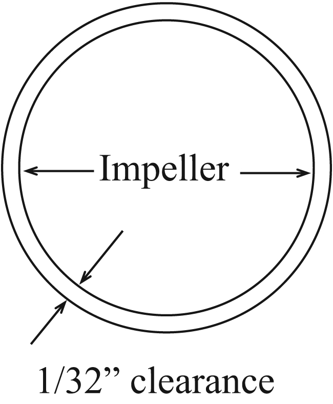
Figure 5. Impeller Eye and Wear Ring
- Remove suction cover or volute case.
- Remove debris from impeller and volute. Remove pebbles lodged between vanes.
- Check wear at the impeller eye and vanes. If worn, repair or replace the impeller.
- Re-machine or replace wear ring if clearance is greater than 1/32 inch per side.
- Replace suction cover or volute. Use a new gasket.
Net Positive Suction Head (NPSH) and Cavitation
Many people are surprised to learn that centrifugal pumps don’t pull water through a suction pipe; they can only pump water that is delivered to them. When air is removed from the suction pipe by a primer pump, the weight of the earth’s atmosphere forces water to rise into the pipe, delivering water to the pump.
Even in the best of circumstances (including a near-perfect vacuum), the maximum water column that can be forced by atmospheric pressure never exceeds about 33 feet in height. As elevation, water temperature, and pipe friction increase, the height of the water column that can be forced drops. The maximum column of water that can be created in a pipe under a given set of conditions is known as Net Positive Suction Head or NPSH.
Insufficient NPSH often occurs at startup. Since the pump is working against low pressure, it pumps a larger volume than in normal operation. This larger volume creates friction losses in the suction line, reducing NPSH. Too little available NPSH can result in vaporization of water in the eye of the impeller, causing cavitation, a noisy condition where vapor bubbles collapse violently in the pump.
To stop cavitation, close the discharge valve. If cavitation is allowed to continue, the impeller and pump casing can become pitted and damaged, reducing pump capacity. To eliminate cavitation as well as water hammer, and to prevent high amperage draw on demand meters, open the discharge valve slowly to fill the mainline whenever you start up the pump.
Caution: Don’t let the pump run more than two minutes with the discharge valve closed.
Servicing the Pump Packing
A pump with shaft sleeve and packing in good condition and properly adjusted shouldn’t require constant re-adjustment, but should be checked daily. Unless proper leakage (about 8 to 10 drops per minute) is running through the packing box, the packing will become overheated and dry out, eventually burning and scoring the shaft sleeve. Excessive dirt, silt, or sand in the water can also score the sleeve.
Figure 6. Pump Packing
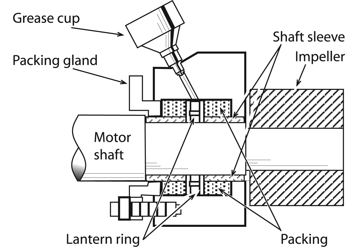
Adapted from: Energy Efficient Pumping Standards, Utah Power & Light Company
Check for an improperly greased or worn rotary shaft seal by running the pump and squirting oil on the shaft just outside the seal. Oil drawn into the seal indicates a leak.
If the pump has been out of service, the packing may be dried and hardened. Air can leak into the pump through the packing box and the pump can lose prime.
Maintenance Tasks
Grease the packing box annually with a proper pump packing grease. Less frequent maintenance causes grease to harden, making this task very difficult.
- If the packing box is equipped with a grease cup or a grease zerk, apply a couple pumps of packing grease to the packing box to force out the remaining water and protect the packing.
- For a packing box without a grease cup or zerk, remove the last two packing rings (see below for replacing packing) and discard. Pack packing grease into the packing box until full. Add two new rings and gently tighten the packing gland slightly to force the grease into the subsequent packing rings. Then loosen the gland.
Replacing the Packing
Old packing should be replaced completely if leakage cannot be reduced by adding a new packing ring to the old packing, or if the packing is burned (dried up and scorched) or has leaked excessively during the season.
Caution: This task is difficult. Have a qualified pump repair shop do it if you are in doubt. If you are attempting the procedure yourself, do it in the shop rather than in the field.
- Remove packing box gland nut with a wrench. Remove the gland and packing.
- To remove packing, twist two packing pullers 180 degrees apart into the exposed packing ring. Pull each ring out of the packing box cavity until all are removed. The lantern ring has two holes 180 degrees apart and can be removed with the packing pullers.
- Replace the shaft sleeve if it is worn or grooved. This usually requires pump disassembly. Once the packing is burned and the shaft sleeve is scored, no amount of adjustment will maintain proper leakage for any length of time.
- Before replacing new packing, insert the packing gland to make sure it enters freely to the gland’s full depth. If it doesn’t, clean out the fragments of old packing and other debris that may be obstructing it.
- Install new packing rings as far forward as can be reached. Install only the type and size of packing recommended by the manufacturer.
- Insert each ring separately. Push it securely into the box and seat it firmly. A small amount of packing grease applied to the packing will make this job a little easier. Don’t use sharp points to push the packing into the box. (Use the packing gland, a wooden dowel, pliers handle, fingers, or other blunt object.) Successive rings of packing should be installed so the joints are 120 degrees apart.
- Install lantern ring (if required) in proper position to the packing rings as shown on your manual’s parts page.
- Install packing gland so that it just begins to enter the stuffing box straight, making sure that the full packing is under uniform pressure.
- Seal the gland with clip, stud, and nut.
- If the packing is equipped with a grease fitting, add a shot of grease.
- Before inserting the last two packing rings on boxes without a grease cup or zerk, pack grease into the packing box until full. Add the last two rings and tighten the packing gland slightly to force the grease into the subsequent rings of packing. Then loosen the gland.
- Start the pump with the packing gland loose so there will be initial leakage. Tighten the packing gland only enough to draw the necessary vacuum for priming.
- Tighten the gland nuts slightly and evenly every 15 to 20 minutes, until leakage is reduced to about 8 to 10 drops per minute and the water leaking from the box is cool.
Caution: Don’t stop leakage entirely.
Centrifugal Pump Shutdown (End of Season)
In cold climates, it is critical that all water be drained from pumps prior to freezing weather.
Maintenance Tasks
- Remove suction and discharge piping in areas where ice is a problem. Make sure drain valves are not plugged, and drain water from the pump.
- Cover any exposed metal, such as the shaft, with protective lubricant to prevent corrosion.
- Cover all oil- or grease-lubricated bearings with lubricant so moisture won’t rust and pit them.
- Remove tension from any belts.
- Open petcock and drain diaphragm-type hand primer.
- If the discharge primer valve is equipped with a rubber seat, coat it with rubber preservative.
- Any rubber parts in a flexible coupling connecting the pump to the driver should also receive a coating of preservative.
- Make sure the ball valve on the pressure gauge riser is closed. Remove the pressure gauge and store inside.
- Seal all openings, including suction, discharge, and primer, with duct tape, to keep out rodents and foreign material.
- Cover the pump with a waterproof tarp.
Turbine Pump Maintenance
General
Some of the instructions below also apply to submersible pumps.
Make a habit of periodically checking that discharge piping is firmly supported in the area near the pump. Make sure the pump is securely bolted to the platform.
If your turbine pump is installed over a well and you’ve experienced water supply problems, check the static level and drawdown in the well. A deeper pump setting might be required.
Figure 7. Oil-Lubricated Turbine Pump
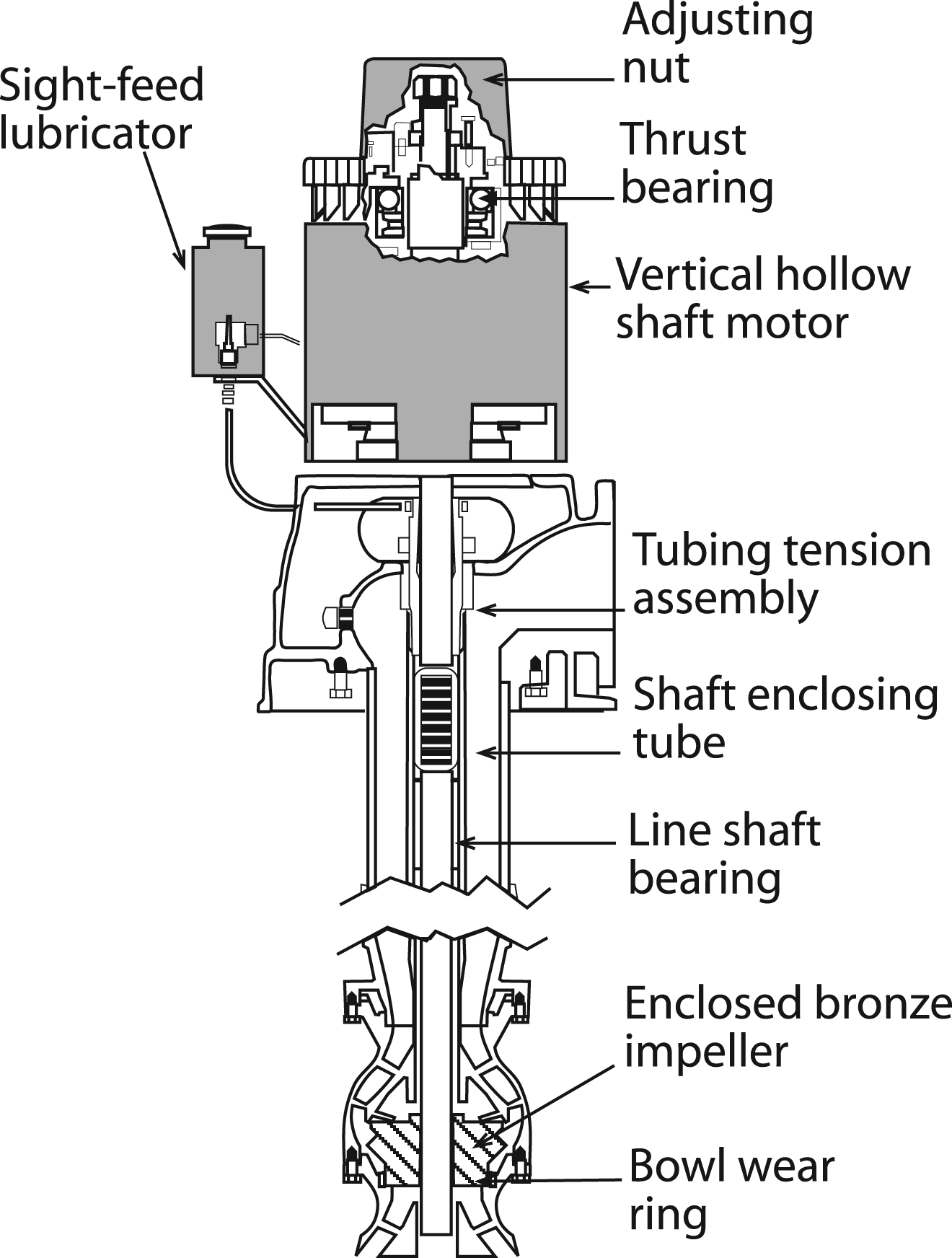
Adapted from: Energy Efficient Pumping Standards, Utah Power & Light Company
Maintenance Tasks
At season startup:
- Change the oil in the oil bath or reservoir for the pump upper bearings. Fill with approved turbine oil almost to the top of the sight glass so bearings are covered, taking care that excess oil doesn’t get on or in the motor.
Periodically:
- Grease lower bearings. Refer to electric motor bearing greasing instructions above.
- Maintain the pump packing on water-lubricated turbine pumps as directed above for centrifugal pump packing.
Annually:
- Change the bearing oil in vertical hollow shaft motors. When replacing the oil, follow motor manufacturer’s recommendations or use ISO-VG32 turbine oil, such as:
— Mobil DTE 797
— Lubriplate HO-0
— Chevron Turbine Oil GST32
— Shell Turbo T Oil 32
Maintain bearing oil at the proper level. Overfilling the oil reservoir can cause oil to overflow when the motor heats up during operation. The excess oil will adhere to the motor and to ventilation screens, collecting dirt and debris and reducing the motor’s ability to dispel heat.
Short-Coupled Turbine Pump
Maintenance Tasks
At season startup for oil-lubricated pumps:
- Fill the oil reservoir and start the oil flowing to the pump one hour before starting the pump. Check to see that the oil tube is filled before running the pump. The pump needs about 10 drops per minute.
At season startup for water-lubricated turbine pumps:
- Pre-lubricate line shaft bearings with light oil.
Periodically:
- Adjust and maintain the packing on water-lubricated, short-coupled turbines as directed for the packing on a centrifugal pump. (See pages 10 to 11 above.)
Annually (or according to manufacturer’s recommended interval) adjust the head shaft nut on short-coupled turbine pumps:
- Remove the top motor cover and take out the set screw.
- Remove, clean, oil, and replace the key stock.
- Loosen the head shaft adjusting nut (it has a left-hand thread) so the shaft and bowls are resting on the bottom. Tighten the head shaft adjusting nut two turns, which will raise the shaft and bowl assembly enough to allow for proper clearance.
- You should be able to turn the shaft by hand once it’s raised. If you can’t, tighten the head shaft adjusting nut one-half turn and try to turn it by hand again.
- Replace the set screw and motor cover.
Caution: If you are unable to turn the shaft by hand, and you have raised the shaft by five or more turns of the nut, remove the pump, disassemble, and inspect for damage or debris. If you have any questions about this procedure, consult your pump dealer.
Deep Well Turbine Pump
Shaft adjustment needs to be more precise for deep well turbines. Shaft stretch needs to be considered. Refer to the manufacturer’s instructions or consult a qualified pump dealer.
Maintenance Tasks
At season startup for oil-lubricated pumps:
- Start lubricating the shaft up to a week before starting the pump, or until the line shaft and column are full of oil and the oil begins to run out at the top near the stretch assembly. During this first week, allow four to five drops of oil per minute. After starting, increase to 10 to 15 drops of oil per minute. Check the manufacturer’s instructions to be sure of the requirement. (Oil will drip slower at night when it cools down.) The viscosity rating of the oil should be 9 or 10.
Periodically:
- Adjust and maintain the packing on water-lubricated deep well turbines, following the same procedures as for the packing on a centrifugal pump. (See above.)
Submersible Pumps
A submersible pump is a turbine pump that is close-coupled to a submersible electric motor. Since both pump and motor are suspended in the water, the drive shaft and bearings required for a deep well turbine pump are eliminated. The pump is located above the motor and water enters the pump through a screen located between the pump and motor.
Submersible pumps use enclosed impellers. The motors are smaller in diameter and longer than turbine pump motors. Inadequate circulation of water past the motor may cause it to overheat and burn out. The riser pipe must be of sufficient length to keep the bowl assembly and motor completely submerged at all times and the well casing must be large for water to easily flow past the motor. Electrical wiring from the pump to the surface must be watertight with sealed connections.
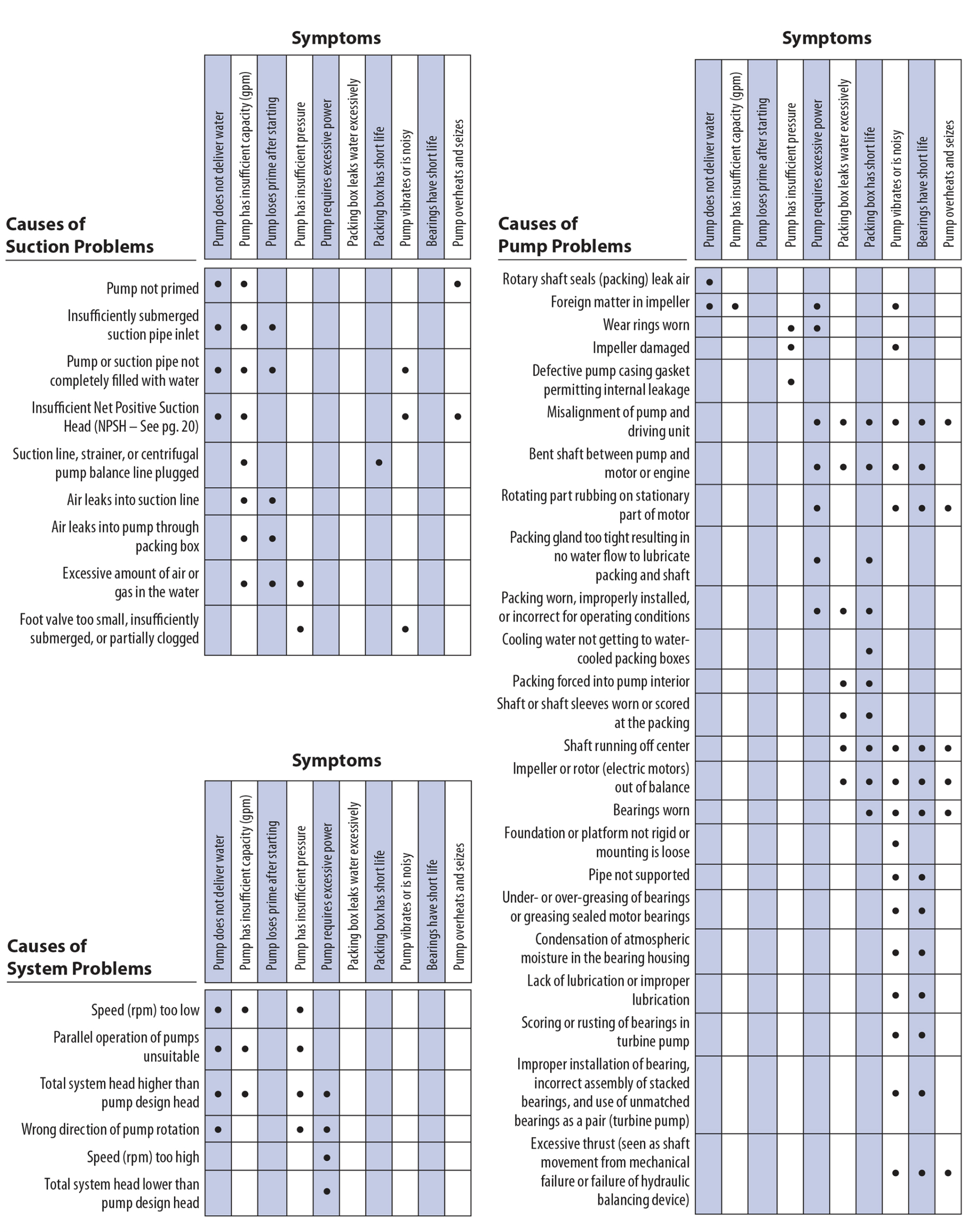
Troubleshooting
This section identifies symptoms and possible causes under Suction, System, and Pump. Find the Symptoms and then look across to the left to see possible causes. Most often, suction problems are the cause. Contact your pump repair shop for additional help.
Caution: This troubleshooting guide is general and does not cover all the possible system configurations or problems that might be encountered.
Table 2-4. Troubleshooting Tables
References
Black, Richard D., and Danny H. Rogers. 1993. Evaluating Pumping Plant Efficiency Using On-Farm Fuel Bills. Kansas State University Cooperative Extension Service, Manhattan, Kansas. 4 p.
Loftis, J.C., and D.L. Miles. 2004. Irrigation Pumping Plant Efficiency. Colorado State University Cooperative Extension Service, Fort Collins, CO. 4 p.
Further Resources
NCAT Publications
The Irrigator’s Pocket Guide. 2004, updated 2023. By Mike Morris, Vicki Lynne, Nancy Matheson, and Al Kurki. National Center for Appropriate Technology, Butte, MT. 161 p.
A take-to-the-field reference to help irrigators save energy, water, and money; includes guidelines for water management, equipment maintenance, and handy conversions and formulas. Get a printed copy by calling 800-346-9140 (toll-free).
Other Publications
Extending Electric Motor Life. Hansen, Hugh J. and Walt L. Trimmer. PNW 292. Oregon State University, Corvallis, OR. 4 p.
Irrigation Energy Saving Ideas. 2000. By Richard F. Beard and Robert W. Hill. Utah State University Extension Service, Logan, UT. 5 p.
Describes factors that affect electric motor performance and service life and describes procedures for controlling internal motor heat.
Irrigation Water Pumps. 1993. By Thomas F. Scherer. Publication AE1057. North Dakota State University Extension Service, Fargo, ND. 12 p.
Covers basic operating characteristics of centrifugal, deep well turbine, submersible, and propeller pumps, as well as pump power requirements and selection criteria.
Maintaining Electric Motors Used for Irrigation. 2000. By Richard F. Beard and Robert W. Hill. Utah State University Extension Service, Logan, UT. 5 p.
Describes factors that affect electric motor performance and service life and describes procedures for controlling internal motor heat.
Irrigation Engineering Publications
University of Nebraska Institute of Agricultural Irrigation
Dozens of publications on irrigation management and hardware.
Wateright
Center for Irrigation Technology at California State University, Fresno.
A “multi-function, educational resource for irrigation water management.” Includes an energy use/cost calculator, guidelines for estimating fuel requirements, options for reducing energy use and costs, and discussions of various other energy-related topics.
Maintaining Irrigation Pumps, Motors, and Engines
Mike Morris and Vicki Lynne, NCAT Agriculture Specialists
© NCAT 2006
IP299
This publication is produced by the National Center for Appropriate Technology through the ATTRA Sustainable Agriculture program, under a cooperative agreement with USDA Rural Development. ATTRA.NCAT.ORG.